The Victron Inverters have a grid input which is passed through on one of the outputs (output 2) which it can still supplement with battery/generator power. If the input is disconnected the inverter goes into island mode (UPS) and only supplies the main AC output (call it essential loads). I think Victron must have had some difficulty with AS2077-2020 as they currently only have the approval mentioned in previous posts. If I had to guess I'd say it was an issue with the new frequency shift requirements being able to remotely throttle the output of the inverter when feeding back to the grid. Just a total guess. I'm not sure why that precluded them from connecting to the grid with no export - as they have an inbuilt anti-islanding relay - maybe it was just the easy path to get an approval.I think we have crossed lines. I'm not talking about what it is is/not permitted but rather what it is capable of.
Some inverter AC inputs are incapable of energising the circuit is supplying them. For them power can only flow in one direction and they can only ever present as a load. As far as the grid is concerned these are no different to a fridge or a hair dryer.
Others however have an AC input which is capable of being bidirectional. It may well be possible in the inverter's settings for it to be set not do so, however it has the capability of energising the grid.


You are using an out of date browser. It may not display this or other websites correctly.
You should upgrade or use an alternative browser.
You should upgrade or use an alternative browser.
Grid Tie Victron ESS with DIY LiFePO4 Battery in Australia - Regulatory Issues?
- Thread starter BipedalPrimate
- Start date
The most common solution to all this is already found in many rural homes- simply having 'most' of the house set up to being on a changeover/transfer switch with 'generator input' (all rural sparkies are quite familiar with doing this, and the regs and gear to do so is commonplace, legally compliant and already fitted to many rural houses because of frequent blackouts in rural areas...)
Then simply adding a completely separate 'standalone' hybrid/offgrid inverter running off the battery bank in offgrid mode, that feeds that generator input...
By simply leaving the 'changeover switch' in the generator position, you have your house totally legally running in 'offgrid' mode, and should you need to revert to the mains power, it is as simple as 'flicking the switch'... (indeed it is possible to even have it fall back to the mains automatically by using a ATS, but effectively 'running in reverse' ie monitoring the inverters output instead of the mains grid power, and should it fail, then switch the house to the 'generator' input (which in this case would be fed from the mains grid) thus restoring power to the house from the mains grid should the offgrid inverter fail for any reason
...
Much simpler, and totally legal (and much easier to get past an inspection lol- it is just a 'power failure generator input' that happens to run 24/7 once the inspection is done...)
;-)
This also 100% guarantees no export ever (unlike some 'software' controlled systems) and is very easy to get done... (you could even if you wanted to, have a separate AS/NZ standards compliant gridtie installation on the 'mains side' of the system to offset the connection fees etc for maintaining the mains grid connection- that would just be a 'standard' gridtie setup (but would not be available for charging the battery bank)
Effectively the 'offgrid system' becomes the 'emergency generator' but happens to run 24/7...
(a lot of the compliance issues is cost related- getting certification is BIG $$$$- and unless they have the market share to justify that cost, it becomes a simple economic exercise- if it is going to take 10 years of sales to recover the cost of certification, then it simply becomes a 'yeah but nah' to the beancounters...)
wattmatters
Solar Wizard
I run like the above - with a manual transfer switch pretty much permanently left in in generator/off-grid supply position, the power for which comes from my AIO inverter.
But I do feed my AIO with grid power from a dedicated (non-backed up circuit) for pass through to loads when I want that (which is most days, as my grid PV is supplying the energy). At night it flips over to run from the battery. It has no capability to back feed the grid through the AIO's AC input - the AIO only acts as a load.
If I add a truckload more PV onto the off-grid AIO then I probably wouldn't need to pass through grid power so often. I have the extra PV there to go up but dealing with a few matters before I get round to doing that.
Although the standard 15A single phase connector commonly used on 'portable' generators has only a 3600W limit, by having a 3 phase input socket and transfer switch used instead (with all three phases joined at the inverters mains output) you are now up to 32A per phase, giving a grand total of 23kW of legal and safe offgrid supply to the house... few systems would max that out... (and again, nothing an electrician couldn't do, using commonly available- and legal- off the shelf components...)


Any electrician will happily wire a house (even a single phase one) with a 3 phase 'emergency generator input wall plug', splitting the various single phase loads across all three phases- at the inverter end its '3 phase wall outlet' is wired the same ie the single phase output of the inverter is connected to all three phase connectors in the outlet...
This is connected at the inverter output, with its single phase output wired to all three Active outputs... (you could even plug a 3 phase diesel genpack into the generator input instead lol- would work just fine...)

- plug in your 3 phase extension cord and bingo- a legal and safe up to 23kW single phase system

(less common but available are the 50A versions which would allow up to 36kW)
That's one hell of an offgrid system.....
As far as inspections go, it stops at that input socket... an electrical inspector doesn't care what happens beyond that- it is simply a 'generator input'- you just happen to be using a sun powered generator instead of a diesel or petrol powered one
;-)
Any electrician will happily wire a house (even a single phase one) with a 3 phase 'emergency generator input wall plug', splitting the various single phase loads across all three phases- at the inverter end its '3 phase wall outlet' is wired the same ie the single phase output of the inverter is connected to all three phase connectors in the outlet...
This is connected at the inverter output, with its single phase output wired to all three Active outputs... (you could even plug a 3 phase diesel genpack into the generator input instead lol- would work just fine...)
- plug in your 3 phase extension cord and bingo- a legal and safe up to 23kW single phase system
(less common but available are the 50A versions which would allow up to 36kW)
That's one hell of an offgrid system.....
As far as inspections go, it stops at that input socket... an electrical inspector doesn't care what happens beyond that- it is simply a 'generator input'- you just happen to be using a sun powered generator instead of a diesel or petrol powered one
;-)
Attachments
Last edited:
wattmatters
Solar Wizard
Apologies, just realised following is not specifically about Victron and regulatory issues but is following on from the discussion on permitted wiring methods.
I hadn't thought about using a 32A x 3-phase cable/plug/power inlet tied together at the AIO's output. But it's a great idea.
I have one limiting factor however which prevents me from doing that, which I'll get to later.
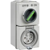
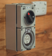
I have the same Hager 63A x 3-phase transfer switch as that pic above but have the three phases on the generator/off-grid supply side tied together in the transfer switch to operate as a single phase output. That was what my original sparky did some years back when we originally set it up. At the time I had a single phase petrol generator and no off-grid AIO solar/battery to use as backup (still have the generator - a Yamaha EF3000iSE).
My transfer switch on the generator input side is supplied via a single phase 32 A cable/plug/power inlet. I have an adapter cord so a 15 A generator outlet can at least supply power via the 32 A power inlet if ever that was needed. The grid side of the switch is powered by the regular 3-phase grid supply.
My 8 kW AIO's output is connected to a single phase 32 A socket/cord which plugs into the transfer switch's 32 A generator power inlet.
I confined myself to an 8 kW AIO since I was using a 32A single phase connection, but an 11 kW or 12 kW single phase AIO using a 3-phase supply cable would be much better as we occasionally sail close to exceeding the 8 kW capacity, and have tripped the AIO's overload once or twice. I'm supplying two occupied dwellings and a large outbuilding, so it's a juggling act at times. I can reasonable manage our loads but not the cottage.
My problem comes when using the system in grid pass through mode (which is roughly half the time) as I have a 32 A per phase mains supply limit.
Since my AIO's AC input is single phase, it's grid supply comes from a single phase. So even if the AIO could supply 12 kW on the output side, I cannot draw more than 32 A (~7.5 kW) for any extended period when operating in grid-pass through mode.
It sucks as my main supply fuses are 63 A but I was required by the distributor to install a 3 x 32 A mains supply circuit breaker.
Still, I sorta wish I'd got the 11 kW version of my AIO so I could ride through the occasional brief draws > 8 kW, as a breaker is not going to trip immediately. 11 kW (very rare) would take about a minute to trip a regular 32 A breaker. Most forays would be more like 8-9 kW and not last for long and a breaker is going to let that go for quite a while.
It wasn't an issue when my elderly Mum lived in the cottage, but she has since passed and it's now occupied by a young couple who tend to have higher power demands. I have some load shedding automations but even those can't help if they are not part of the load.
If my main supply breaker was 3 x 63 A then I'd go for this solution. That restriction makes it very tricky.
Although the standard 15A single phase connector commonly used on 'portable' generators has only a 3600W limit, by having a 3 phase input socket and transfer switch used instead (with all three phases joined at the inverters mains output) you are now up to 32A per phase, giving a grand total of 23kW of legal and safe offgrid supply to the house
I hadn't thought about using a 32A x 3-phase cable/plug/power inlet tied together at the AIO's output. But it's a great idea.
I have one limiting factor however which prevents me from doing that, which I'll get to later.
I have the same Hager 63A x 3-phase transfer switch as that pic above but have the three phases on the generator/off-grid supply side tied together in the transfer switch to operate as a single phase output. That was what my original sparky did some years back when we originally set it up. At the time I had a single phase petrol generator and no off-grid AIO solar/battery to use as backup (still have the generator - a Yamaha EF3000iSE).
My transfer switch on the generator input side is supplied via a single phase 32 A cable/plug/power inlet. I have an adapter cord so a 15 A generator outlet can at least supply power via the 32 A power inlet if ever that was needed. The grid side of the switch is powered by the regular 3-phase grid supply.
My 8 kW AIO's output is connected to a single phase 32 A socket/cord which plugs into the transfer switch's 32 A generator power inlet.
I confined myself to an 8 kW AIO since I was using a 32A single phase connection, but an 11 kW or 12 kW single phase AIO using a 3-phase supply cable would be much better as we occasionally sail close to exceeding the 8 kW capacity, and have tripped the AIO's overload once or twice. I'm supplying two occupied dwellings and a large outbuilding, so it's a juggling act at times. I can reasonable manage our loads but not the cottage.
My problem comes when using the system in grid pass through mode (which is roughly half the time) as I have a 32 A per phase mains supply limit.
Since my AIO's AC input is single phase, it's grid supply comes from a single phase. So even if the AIO could supply 12 kW on the output side, I cannot draw more than 32 A (~7.5 kW) for any extended period when operating in grid-pass through mode.
It sucks as my main supply fuses are 63 A but I was required by the distributor to install a 3 x 32 A mains supply circuit breaker.
Still, I sorta wish I'd got the 11 kW version of my AIO so I could ride through the occasional brief draws > 8 kW, as a breaker is not going to trip immediately. 11 kW (very rare) would take about a minute to trip a regular 32 A breaker. Most forays would be more like 8-9 kW and not last for long and a breaker is going to let that go for quite a while.
It wasn't an issue when my elderly Mum lived in the cottage, but she has since passed and it's now occupied by a young couple who tend to have higher power demands. I have some load shedding automations but even those can't help if they are not part of the load.
If my main supply breaker was 3 x 63 A then I'd go for this solution. That restriction makes it very tricky.
One way around that would be ignoring any mains feedthrough altogether, just run from the inverter fulltime, with a high capacity charger fed from the mains and set so that doesn't do much normally (ie the solar provides the bulk of the charging, with the mains charger only used when the battery bank is well down... ie max charge voltage is set lower than normal, so it kicks in on low bank voltage, but stops again when the bank is still well from being fully charged
This is a common tactic used in many offgrid systems with an automatic generator start backup- you don't 'want' the generator to run for a long period ($$$ for fuel) to fully recharge the battery bank, just provide the power enough to keep things running until the sun comes up again... then let the solar do the rest for free...
Best of all, with the auto start genpacks for a fully offgrid system- its all totally automatic- the genpack starts up at the 'critical' level, and only puts in enough to 'top it up a bit, then shuts down again- should the batteries drop enough again, it repeats until the solar does the rest of the bulk charge...
So effectively the entire system runs off the battery bank permanently, until the batteries are depleted to whatever level you set as your 'critical' level say 20% left, then the genny kicks in and runs for a short while (boosting up the charge partially say to 40%) and leaving the rest for the solar to do for free- by careful voltage selection, it is easy to do all this simply by selecting the appropriate volts low and max charge volts limits...
It does rely on the system being capable of handling the full loads (or multiple smaller systems each doing part of the loads) and in this case the mains grid takes the place of the 'backup' genny, with the offgrid inverter taking the place of the mains...- basically a standard system but running in reversed roles...
This is once again, something that is possible to do with already existing certified gear, making it much easier to do than trying to get past an inspection with non certified gear... (and of course once the electrical inspector has signed off, then you can do whatever you please on the 'offgrid' side legally lol- want more panels or more battery storage or a bigger inverter (up to the limits of the input)- just fit it and run...)
The other advantage is that in a pinch, you can just 'flip a switch' and it becomes a bog standard mains wired house- with increased bills of course- but should you have an equipment failure for any reason- you aren't left stranded or relying on a generator..., you still got that huge 'Gigawatts generator' running in from the street ;-)
wattmatters
Solar Wizard
You sure are full of good ideas!One way around that would be ignoring any mains feedthrough altogether, just run from the inverter fulltime, with a high capacity charger fed from the mains and set so that doesn't do much normally (ie the solar provides the bulk of the charging, with the mains charger only used when the battery bank is well down... ie max charge voltage is set lower than normal, so it kicks in on low bank voltage, but stops again when the bank is still well from being fully charged
I have a spare 4 kW AIO which can act as a charger.
Indeed I recently hooked up this spare AIO to the home battery so I could test out using our EV's V2L as a means of providing supplemental charge if we had an extra long outage (instead of using a generator). I ran the test for 11 hours and took 22 kWh out of the car.
It is already completely monitor-able and controllable with Home Assistant, so charging can be controlled with automations, turning on/off as required and charge current can be ramped up/down as needed and/or based on available excess grid PV. It has a max grid charge current of 60 A DC, so ~ 3kW. These are the parameters I can control from Home Assistant (and there are dozens of other parameters I can monitor):


It is an extra energy overhead to use a second AIO but conceptually this would work well. The inverter can remain in power saving mode as it is not supplying loads.
I already have a 32 A power outlet which currently supplies the primary AIO's AC input. That power outlet could instead feed the spare AIO and charging can be managed with that, leaving the primary AIO to run from off-grid battery/solar all the time.
I really like this idea as I do very much dislike the primary AIO's switching between Utility mode and Solar/Battery mode each day.
I may even have a spare 32 A plug I can use.
I'm going to spend a bit more time thinking this one through some more...
I been in the electrical trade since the 1980's (did my apprenticeship as an elec fitter on the railways) offgrid solar since about the same time, and got my gridtie installation and design ticket back in 2004- so had a 'little' experience with 'working around the bloody minded inspectors' that just want to have 'carbon copy' installs and are totally out of their depth when it comes to anything they haven't seen done before...
Done quite a bit of commercial work (where many inspectors have never even seen a solar install ever until recently) as well as those adding battery backup in the 'olden days' before they became the norm- many inspectors were simply 'nah hah' when it came to having a battery on gridtie solar systems, and many of us found 'legal work arounds' to get past them lol
You have to remember that many inspectors have literally zero electrical experience!!! they just have a list of things to look for and want to 'tick all the boxes' on their form- they literally don't know what to do when it isn't covered by their limited training...
Animalector
New Member
- Joined
- Sep 19, 2020
- Messages
- 7
just be cautious, my AIO sungrow battery output is not isolated from mains input so DC coupling might not work the way you wantYou sure are full of good ideas!
I have a spare 4 kW AIO which can act as a charger.
Indeed I recently hooked up this spare AIO to the home battery so I could test out using our EV's V2L as a means of providing supplemental charge if we had an extra long outage (instead of using a generator). I ran the test for 11 hours and took 22 kWh out of the car.
It is already completely monitor-able and controllable with Home Assistant, so charging can be controlled with automations, turning on/off as required and charge current can be ramped up/down as needed and/or based on available excess grid PV. It has a max grid charge current of 60 A DC, so ~ 3kW. These are the parameters I can control from Home Assistant (and there are dozens of other parameters I can monitor):
View attachment 211013View attachment 211014
It is an extra energy overhead to use a second AIO but conceptually this would work well. The inverter can remain in power saving mode as it is not supplying loads.
I already have a 32 A power outlet which currently supplies the primary AIO's AC input. That power outlet could instead feed the spare AIO and charging can be managed with that, leaving the primary AIO to run from off-grid battery/solar all the time.
I really like this idea as I do very much dislike the primary AIO's switching between Utility mode and Solar/Battery mode each day.
I may even have a spare 32 A plug I can use.
I'm going to spend a bit more time thinking this one through some more...
wattmatters
Solar Wizard
This morning I hooked up the spare AIO for charging the battery. Unfortunately it looks as though the comms in my AIO is toast.I'm going to spend a bit more time thinking this one through some more...
Comms were a bit intermittent to begin with, I did a bit of fiddling with settings and comms came alive and I was able to adjust parameters as normal. All good I thought, so I started it up charging the battery, and then set about writing some automations for it.
It was charging the battery just fine but at some point the comms were lost again and I was unable to revive them, trying everything I could think of. With that I lost any remote control I had. Naturally my new automations would not work.
So I disabled it and turned back on all the automations for my existing set up.
I've fired off an email to Solar Assistant support in case they have any bright ideas on what I may have missed with the AIO comms but I have a feeling the comms are toast. It still works as a charger and all the settings are accessible and adjustable from the AIO display panel, and that's handy for the using the EV V2L for supplemental charging as I just set one charge level and leave it but for this application I need the automated management to be working.
Bummer. Will see if there's some way to revive the comms but I'm not holding out any great hope.
Today I received the following information from Ausgrid (the network I'm on) which I think is good news. In response to my question - can I hook the Victron Multiplus II 48V/5000 230V up to the Ausgrid network I received the following reply:
"Thanks for getting in touch with Ausgrid.
We will allow the Victron Multiplus II 48/ 5000 230V Inverter to be connected to the Ausgrid network provided that its installation is compliant with AS/NZS 4777.1, AS/NZS3000, Ausgrid Standard NS194 and any other relevant standards.
The Inverter itself must be compliant with AS/NZS 4777.2. I believe that the Victron Multiplus II 48/ 5000 230V does not comply with Australia A protection settings out of the box. Hence prior to commissioning the inverter, the Australia A protection setting must be uploaded to the inverter.
Photo/s showing the uploaded Australia A settings on the inverter, and including the serial number of the inverter are to be then sent to eg@ausgrid.com.au with the email referencing the Ausgrid application web reference number."
Can some of you more experienced players confirm that this means the Victron can now be connected with no mains protection relay? It does seem that provided the Australia A settings are uploaded to the inverter that it now satisfies the anti islanding requirements set out in Ausgrid NS194 but that is a long document")
"Thanks for getting in touch with Ausgrid.
We will allow the Victron Multiplus II 48/ 5000 230V Inverter to be connected to the Ausgrid network provided that its installation is compliant with AS/NZS 4777.1, AS/NZS3000, Ausgrid Standard NS194 and any other relevant standards.
The Inverter itself must be compliant with AS/NZS 4777.2. I believe that the Victron Multiplus II 48/ 5000 230V does not comply with Australia A protection settings out of the box. Hence prior to commissioning the inverter, the Australia A protection setting must be uploaded to the inverter.
Photo/s showing the uploaded Australia A settings on the inverter, and including the serial number of the inverter are to be then sent to eg@ausgrid.com.au with the email referencing the Ausgrid application web reference number."
Can some of you more experienced players confirm that this means the Victron can now be connected with no mains protection relay? It does seem that provided the Australia A settings are uploaded to the inverter that it now satisfies the anti islanding requirements set out in Ausgrid NS194 but that is a long document
davidpb153
New Member
One way around that would be ignoring any mains feedthrough altogether, just run from the inverter fulltime, with a high capacity charger fed from the mains and set so that doesn't do much normally (ie the solar provides the bulk of the charging, with the mains charger only used when the battery bank is well down... ie max charge voltage is set lower than normal, so it kicks in on low bank voltage, but stops again when the bank is still well from being fully charged
The problem with this is that one needs to buy a ton of equipment that the Multiplus already provides, and the multiplus has come down a lot in price and is starting to look like quite good value.
For example, suppose I go Grid -> Charger (with smart switch) -> Battery -> Multiplus -> smart relay -> ATS (with Grid and multiplus input, multiplus as priority) -> Load.
With this setup, I could:
- Charge the multiplus during the day using excess solar (smart switch needed to ensure only excess solar is used)
- Optionally cut off output power from the multiplus to feed the load directly from the grid (using the smart relay), avoiding losses (make sense if have excess solar production).
It is hard to get a charger as good as the multiplus, while the ATS and smart relay emulate the UPS that's already in the multiplus.
Basically, I create a system that is not quite as good as the multiplus, and multiple points of failure, potentially lower efficiency.
(As an aside, one thing I don't quite get is how is if/why a multiplus is allowed to charge batteries from the grid as part of an RV/bus/truck. If the AC input is connected to say a plug in the RV, then surely it is no different to having the AC input connected to a plug in a home? In which case, why couldn't you use the multiplus to charge your batteries?)
On the other hand, if we go with the grid protection relay (say about 25% more cost than a decent charger and ATS), we get a better system, and potentially a bonus in that it may be allowed to feedback to the grid (which when solar FIT tariffs change to be time based could be valuable)? (At least I think from @bimedalprivate description, it is legally allowed - not just capable - to feedback to the grid).
Today I received the following information from Ausgrid (the network I'm on) which I think is good news. In response to my question - can I hook the Victron Multiplus II 48V/5000 230V up to the Ausgrid network I received the following reply:
"Thanks for getting in touch with Ausgrid.
We will allow the Victron Multiplus II 48/ 5000 230V Inverter to be connected to the Ausgrid network provided that its installation is compliant with AS/NZS 4777.1, AS/NZS3000, Ausgrid Standard NS194 and any other relevant standards.
The Inverter itself must be compliant with AS/NZS 4777.2. I believe that the Victron Multiplus II 48/ 5000 230V does not comply with Australia A protection settings out of the box. Hence prior to commissioning the inverter, the Australia A protection setting must be uploaded to the inverter.
Photo/s showing the uploaded Australia A settings on the inverter, and including the serial number of the inverter are to be then sent to eg@ausgrid.com.au with the email referencing the Ausgrid application web reference number."
Can some of you more experienced players confirm that this means the Victron can now be connected with no mains protection relay? It does seem that provided the Australia A settings are uploaded to the inverter that it now satisfies the anti islanding requirements set out in Ausgrid NS194 but that is a long document
From what I can tell, although the Multiplus II can meet some of the Australia A protection settings such as the Volt-Var and Volt-Watt responses; I think there are other settings such as ROCOF (rate of change of frequency), Vector Shift, and sustained operation (10mins of average 258V or above), which make it unable to be compliant - and I'm guessing that's why Victron hasn't pursued compliance and explicitly state that the inverter is not AS/NZS 4777.2 compliant and must not be connected to the grid. It does seem that the multiplus does have a ROCOF limit as evidenced by someone here:
https://community.victronenergy.com...ii-481000-disconect-fron-grid-with-rocof.html
It's not clear what the ROCOF limit is. For Australian compliance it needs to withstand up to +/-4Hz change per second. Above which it must turn off, if my understanding is correct. I've checked some past compliance test reports of the multiplus II, such as here:
https://heliosps.com/wp-content/upl...-AS-NZS-4777.2-MultiPlus-II-48-3000-35-32.pdf
and here:
https://www.ena-eng.org/gen-ttr/TTf1l3s/VICEN_02689_221115094139.pdf
But they were only tested up to 0.95Hz per second at most. So it's not clear to me what the ROCOF limit is for the Multiplus. It is possible though that it is compliant and just hasn't been tested. But since it can't be changed in the settings - without a firmware change it may be fixed. Unless it does change with the grid code settings and the user cannot see what this setting changes to. Likewise with Vector Shift - I'm not sure what the limit is as past compliance tests only show that the inverter can withstand a certain amount, but wasn't tested to see at what point the inverter triggers the AC transfer switch to disconnect from the grid.
Then there is the 10 min of average grid voltage of 258V or above. Without a firmware update, I don't think this feature exists; and from what it sounds like Victron doesn't seem interested in pursuing compliance.
I suspect it is simply a cost/benefit tradeoff- Victron don't sell that many inverters (and most of their users are offgrid anyway) and getting compliance testing done is EXPENSIVE!!!From what I can tell, although the Multiplus II can meet some of the Australia A protection settings such as the Volt-Var and Volt-Watt responses; I think there are other settings such as ROCOF (rate of change of frequency), Vector Shift, and sustained operation (10mins of average 258V or above), which make it unable to be compliant - and I'm guessing that's why Victron hasn't pursued compliance and explicitly state that the inverter is not AS/NZS 4777.2 compliant and must not be connected to the grid. It does seem that the multiplus does have a ROCOF limit as evidenced by someone here:
https://community.victronenergy.com...ii-481000-disconect-fron-grid-with-rocof.html
It's not clear what the ROCOF limit is. For Australian compliance it needs to withstand up to +/-4Hz change per second. Above which it must turn off, if my understanding is correct. I've checked some past compliance test reports of the multiplus II, such as here:
https://heliosps.com/wp-content/upl...-AS-NZS-4777.2-MultiPlus-II-48-3000-35-32.pdf
and here:
https://www.ena-eng.org/gen-ttr/TTf1l3s/VICEN_02689_221115094139.pdf
But they were only tested up to 0.95Hz per second at most. So it's not clear to me what the ROCOF limit is for the Multiplus. It is possible though that it is compliant and just hasn't been tested. But since it can't be changed in the settings - without a firmware change it may be fixed. Unless it does change with the grid code settings and the user cannot see what this setting changes to. Likewise with Vector Shift - I'm not sure what the limit is as past compliance tests only show that the inverter can withstand a certain amount, but wasn't tested to see at what point the inverter triggers the AC transfer switch to disconnect from the grid.
Then there is the 10 min of average grid voltage of 258V or above. Without a firmware update, I don't think this feature exists; and from what it sounds like Victron doesn't seem interested in pursuing compliance.
I don't know what it would cost to get it done, but it is BIG $$$- I know just for a simple testing done for mains power supplies (which don't actually act as a generating source) it cost the company that I used to work for over fifty thousand dollars for a 'model' testing (covered all devices with the same circuitry internally) but if we changed anything, then it would have to undergo testing again to ensure the new design was still compliant...
I'd hate to think of what it costs to get a hybrid inverter tested (as it has both generation capabilities as a gridtie, PLUS self generation for islanding)- which means all sorts of safety features that would have to be tested and possible fault modes checked for...
After all they not only have to meet the auto shutdown requirements of a gridtie inverter for export limitations, but also the safety requirements for island operations...
They may have simply looked at the likely cost, and sales figures, and walked away...
BipedalPrimate
New Member
- Joined
- Mar 25, 2022
- Messages
- 63
The announcement for 510 in the Victron Professional News section states:Am I correct in assuming that Victron now had CEC approval in Australia for the MP II grid code A/477.2:2020 with new Appendix M approval ???
I assume this due to the details within the changelog of the MP Firmware 510 that states >>>
**Enabled the appendix M. gridcodes of AS/NZS4777 for standard Multis/Quattros.
(installation requires external IP)**
Enabled the appendix M. gridcodes of AS/NZS4777 for standard Multis/Quattros (installation requires external Island Protection)
So external IP means Island Protection hence a Grid Protection Relay.
However, as at today the Clean Energy Council Approved Inverters list still shows Stand Alone Inverter With Generator Input Battery Only
So, no, CEC approval has not changed.
Similar threads
- Replies
- 7
- Views
- 496
- Replies
- 1
- Views
- 234
- Replies
- 1
- Views
- 378
- Replies
- 0
- Views
- 453