diy solar

diy solar

Ground Loop Question

DerpsyDoodler

Solar Addict
Joined
Jan 10, 2021
Messages
2,247
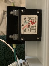
I have a ground fault device i plan on installing between my solar system and my battery bank. The installation instruction diagram is in the below pic:

738594B5-5ADE-4C66-A8A7-97916E521654.jpeg

My DC negative bus bar (which is depicted as "terminal bus bar" in the diagram) is bonded to ground. if I were to install the gfdi breaker as depicted in the diagram, wouldnt that effectively create a ground loop between my DC negative bus and my ground bus? Is that by design? Should I not bond my DC negative bus bar to ground?
 
I think you want your bonded ground to only go through the GFID that way it’ll isolate the battery positive if it notices substantial leakage on your bonded ground.

so yeah pull that bonded ground off your batt negative bus bar.
 
I think you want your bonded ground to only go through the GFID that way it’ll isolate the battery positive if it notices substantial leakage on your bonded ground.

so yeah pull that bonded ground off your batt negative bus bar.
Not sure what you mean by "isolate battery positive". That's not what this gfdi is designed for. in the case that this GFDI trips, it is intended to disconnect/isolate the solar system from the rest of the dc bus
 
Sorry terminology issue on my end, it opens positive contacts to the SCC.
OK. Since that's clear, I presume I should still disable the ground bond? I have two problems with doing that.
1. My DC bus ground bond is 4/0 cable. the ground wire on/through the GFDI is 10awg.

2. Furthermore, if GFDI trips, the negative dc bus would no longer be connected to ground.

Is any of this a concern?
 
What kind of faults were you expecting where you needed 4/0?

Transmission equipment in 115kv substations is bonded with only 1/0, that’s parraelled for 345kv yards.

If the GFDI operates wouldnt that 43k ohm resistor still tie your bus bar to ground?
 
What kind of faults were you expecting where you needed 4/0?

Transmission equipment in 115kv substations is bonded with only 1/0, that’s parraelled for 345kv yards.

If the GFDI operates wouldnt that 43k ohm resistor still tie your bus bar to ground?
Inverter is wired with 4/0, so I wanted to either match that or go 1awg lower (this is what inverter recommended for its chassis ground, so I applied the same logic to the DC ground).

I had overlooked that. I suppose the 43k ohm would still keep it grounded, but would it allow enough current flow to trip a breaker or blow a fuse? I presume that should be a concern or am I mistaken?
 
Bump - concern still not addressed.
You need to disconnect the ground from your DC negative, and have that ground connection go through the GFDI device. If you leave it connected, you are effectively bypassing the device by providing a path to ground that doesn't go through it. If you do that, it won't operate properly.

This is probably why they call this point a "terminal bus bar" as it is not supposed to grounded.
 
You need to disconnect the ground from your DC negative, and have that ground connection go through the GFDI device. If you leave it connected, you are effectively bypassing the device by providing a path to ground that doesn't go through it. If you do that, it won't operate properly.
Yep, got that much. My final concern is stated in the last paragraph of post #7 (top right corner of each post has a number, you don't have to count! lol).

This is probably why they call this point a "terminal bus bar" as it is not supposed to grounded.
Oh ok. Subtle differences in terminology i wasn't aware of. Thanks for enlightening.
 
I think there is a coil across that 43k resistor soon as ground current increases enough it trips the GFDI, isolating the system and bypassing the resistor and latching shut.
 
couple more pics:
 

Attachments

  • A529D1FB-0193-4B0F-B9A8-C4A980062CBE.jpeg
    A529D1FB-0193-4B0F-B9A8-C4A980062CBE.jpeg
    157.5 KB · Views: 6
  • 74479DF8-F171-47DD-90FB-FD132029AC10.jpeg
    74479DF8-F171-47DD-90FB-FD132029AC10.jpeg
    142.8 KB · Views: 6
Agreed, but you’re also not seeing the contacts that open up either ?

something is sensing the ground current to trip the contacts.
 
Agreed, but you’re also not seeing the contacts that open up either ?

something is sensing the ground current to trip the contacts.
Right, ok. So circling back around to my concerns with disabling the DC bus ground:

I suppose the 43k ohm resistor would still keep the dc negative bus grounded, but would it allow enough current flow to trip a breaker or blow a fuse? I presume that should be a concern or am I mistaken?
 
Right, ok. So circling back around to my concerns with disabling the DC bus ground:

I suppose the 43k ohm resistor would still keep the dc negative bus grounded, but would it allow enough current flow to trip a breaker or blow a fuse? I presume that should be a concern or am I mistaken?
It is not a concern. The resistor only comes into play after the GFDI opens. There is no current flowing after that. The 43k keeps the terminal bus bar to stay at ground potential, while being a high enough value that dangerous current can't flow.
 
It is not a concern. The resistor only comes into play after the GFDI opens. There is no current flowing after that. The 43k keeps the terminal bus bar to stay at ground potential, while being a high enough value that dangerous current can't flow.
The GFDI opens, which severs the DC bus connection to ground (and disconnecting scc positive terminals from the system). Current will still be flowing through dc bus circuit (between batteries and inverter).

That presents a situation where DC bus is providing electrical service but has only a 43k ohm connection to ground.

Sorry if I am reiterating what you understand and am telling me i shouldn't be concerned with. I just want to make sure you understand me correctly and I understand you correctly.
 
Per that diagram the GFDI only protects for issues of the array or SCC, your inverter would need to be connected to the GFDI as well if you want that protected, but then you’d need to be concerned for the low 80A rating.
 
Per that diagram the GFDI only protects for issues of the array or SCC, your inverter would need to be connected to the GFDI as well if you want that protected, but then you’d need to be concerned for the low 80A rating.
I wasnt implying the breaker should protect the inverter, too.

What I am trying to impress upon this thread, in no uncertain terms, is that if i remove the ground bond from the DC bus, in favor of using the bond through the GFDI, when/if (hopefully never right?) the GFDI trips, I will still have a live DC bus, but now with only a 43k ohm connection to ground. Is this an acceptable, safe, codified operating state?
 
I believe if the GFDI trips (opens the positive contact, and closes the ground contact) such as there is a direct path to the bonded ground, this would be very similar to Lightning arresters, high impedance until flash over then direct short to ground to isolate and touch potential.

What’s the impedance of those ground contacts when nothing is connected? Try and trip the relay and check the contact impedance again.
 
Back
Top