diy solar

diy solar

Ground Neutral Bonding: What is this and when do I need it?

CarlCruzin

New Member
Joined
Oct 14, 2020
Messages
90
Location
Nevada
I am in the process of wiring up my inverter and batteries. I have heard a lot about ground-neutral bonding and hazards associated with doing it incorrectly.

I am having difficulty finding when and why to bond the ground to the neutral. I couldn't find it addressed in my manual, and I assume that is because it is not of concern, but I want to double check since it is a safety concern.
(Sungoldpower 4kw 48v Pure sine Inverter/charger/ATS) https://cdn.shopifycdn.net/s/files/1/0323/4090/2025/files/LFP_Manual_sungoldpower.pdf?v=1639022296

I'm not sure if it's necessary, but I had extra transfer switch spots so I am switching to the generator neutral when on self-contained Generator/inverter power, and switching to the shore power neutral when on shore power.
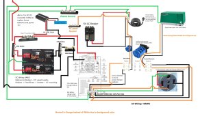
ACWiringDiagramSinglePhaseGenWithMTS__RV_ONLY.jpg
 
Almost all houses are "bonded" in your main panel.... Some are bonded in the meter panel...

If you leave the neutrals and power wires as individual wires all will be fine...

The problem is if the neutral gets connected to the ground wire in more then one spot then the ground can then carry neutral current and that can be bad...
 
There are several resources in the resources area on this topic. Here is the link to the first


and Electricians U did a video on the topic just this week that was very good
 
I am in the process I had extra transfer switch spots so I am switching to the generator neutral when on self-contained Generator/inverter power, and switching to the shore power neutral when on shore power.

View attachment 84303
Caveat - did not study your drawing

I personally like that arrangement, however.
I don’t think it violates any rules either.
 
Not expert with these inverter/chargers. But my reading of the manual indicates there is ac neutral. That means the inverter has some internal means to handle that. Don't do anything other than the wiring diagram shows. Read the two warnings on the bottom of page 17.
I would have a better shore earth(green) to chassis connection. It is a safety issue.
Well I'm sure I look dumb because that clearly addresses my concern. I was going off a downloaded manual from about 6mo ago and they obviously updated it since. I linked to the website link because I figured it was the same manual! :LOL:
 
  • Like
Reactions: Zil
Side note: I finished wiring the system earlier and ran it through a few tests. It works great! Easily runs both AC units while only pulling about 36A from the batteries. Kicked on the generator and it went to bypass as well as started recharging the battery pack. I can't wait to add the solar panel setup
 
Grounding is basically introducing a know fault condition on purpose. The idea is that from there you can detect other faults with fuses. Nowadays there are better ways to protect circuits, people and pets, but we don't because of costs, tradition and backwards compatibility.

When I did my electricians exam so many years ago, one of the questions was why the ground wire had to be half the diameter of the neutral wire between breaker boxes (in each neutral and ground were bonded), the answer they wanted to hear was "So that the ground wire does not carry the neutral current" which I knew was wrong, but in order to pass the exam, it was the answer I gave. I did point that out to the teacher and a couple of inspectors, and the code was changed. Unlikely any one listened to me, but still.

One of the problems that can occur is ground loops when the neutral shorts elsewhere to ground and that won't be detected. Another one is with data cables where the shield, if bonded to ground in two places, can carry neutral current and introduce noise. But if you want to pass inspections, we just follow the rules and don't ask too many questions.
 
In that case you can’t wire a nema 14-50 outlet as that require split phase. Connecting L1 and L2 to same phase as you have it in your wiring diagram will not make it a 240V outlet.
Welcome to the forum jonas.

I was assuming there were no 240 loads to power. Without any 240 loads the wiring would move 120 around just fine, right?
 
It would but it depends on what the RV expect. If the RV use split phase just to distribute the load between L1 and L2 and neutral then it should work to “fake” a split phase.
My rv generator has a single phase output that is distributed by two 30A breakers to the nema 14-50 outlet. I selected a single phase inverter so it would be compatible and bypass easily. There are no 240v loads so I have the output bridged for the generator, now being directed to the inverter/charger/ats, whose output is now what supplies both legs of the 14-50 outlet.

When plugged into the rv 14-50 outlet power will be drawn from the inverter. When the generator is started and once the voltage stabilizes, the inverter will bypass the generator power and draw up to 1900w to charge the battery packs.

When I plug into shore power, one of the legs will branch off to the inverter so it can recharge the packs
 
Last edited:
Back
Top