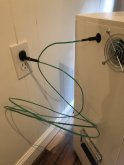
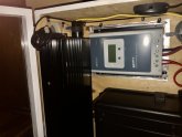
I’ve built a 24v 2.4kw system that I will be using entirely stand-alone/unbonded for emergency backup, camping, and off-grid homestead setup. The (Xijia) inverter has built-in 8x protection and outlets I’ve run from it are GFCI protected, even though it will be used indoors/protected. The system is setup in an open-faced wooden box. Do I need to add any grounding? I was thinking of running copper from the inverter and charge controller out the box and bonding to the frame of an aluminum hand truck that I’ll soon be adding to move this unit around. Is that even necessary given my expected use? Appreciate any thoughts!
You are using an out of date browser. It may not display this or other websites correctly.
You should upgrade or use an alternative browser.
You should upgrade or use an alternative browser.
Grounding for a Portable Power Station?
- Thread starter SolarOhio
- Start date
If the inverter has grounding points, it should be grounded to earth if you are using it to power items that are ground protected (do they have 3 prongs on the cord?)
Inverter does have a grounding point. Will it in effect be “case grounded” if I wire to the metal on the external dolly? Or could I add a single grounding wire/clamp to the setup that can be tied-in to my home’s ground or a rod added to our off-grid? It’s kind of setup like an over-sized Kodiak minus the RV plug, so I’m wondering how grounding is covered for those units in a totally remote situation.
If the inverter has grounding points, it should be grounded to earth if you are using it to power items that are ground protected (do they have 3 prongs on the cord?)
Excuse my ignorance on the subject, but what would be the benefit of earth ground in this context?
I would've assumed an equipment ground connection from the inverter chassis to the batter negative or a gounding/negative bus would be enough, but I certainly don't have a handle on the details of proper grounding, or know much about portable power stations.
Last edited:
Just my opinion. Not sure what the rule is.
With standard home wiring, a GFCI protected outlet provides shock/electrocution protection regardless of the ground. In fact for appliances with only 2 prongs on their plugs, the ground connection is not even used. The NEC accepted way to convert a 2 prong to 3 prong outlet without a ground is to use a GFCI receptacle and label it with "no equipment ground". For a portable power station I don't see why you would earth ground it when it's meant to be mobile, so the only choice I see is using GFCI which you already are doing.
With standard home wiring, a GFCI protected outlet provides shock/electrocution protection regardless of the ground. In fact for appliances with only 2 prongs on their plugs, the ground connection is not even used. The NEC accepted way to convert a 2 prong to 3 prong outlet without a ground is to use a GFCI receptacle and label it with "no equipment ground". For a portable power station I don't see why you would earth ground it when it's meant to be mobile, so the only choice I see is using GFCI which you already are doing.
Not exactly.Just my opinion. Not sure what the rule is.
With standard home wiring, a GFCI protected outlet provides shock/electrocution protection regardless of the ground. In fact for appliances with only 2 prongs on their plugs, the ground connection is not even used. The NEC accepted way to convert a 2 prong to 3 prong outlet without a ground is to use a GFCI receptacle and label it with "no equipment ground". For a portable power station I don't see why you would earth ground it when it's meant to be mobile, so the only choice I see is using GFCI which you already are doing.
Ungrounded outlets protected by gfci function because the REST of the system, the home plumbing, and the grid supply to the home IS grounded to earth, and the neutral.
An earth ground is required on a system that is NOT designed to be mobile. Which is why I specified "if it has a ground point on the case of the inverter" a truly mobile design is isolated from ground, and has no grounding provisions.
An earth ground is required on a system that is NOT designed to be mobile. Which is why I specified "if it has a ground point on the case of the inverter" a truly mobile design is isolated from ground, and has no grounding provisions.
But in that case (truly mobile or otherwise isolated from earth-ground) I was under the impression the best practice was to give the inverter chassis a return path to the source (i.e. connect the inverter ground point to the battery negative), maybe I'm misinterpreting something though.
Most inverters I've looked at have language similar to the below in the manual or install instructions, its possible I'm not correctly interpreting it:
Xantrex X
Grounding Locations
You must connect the equipment ground lug to a grounding
point—usually the vehicle’s chassis or DC negative bus ground
Victron Phoenix
This is a Safety Class I product (supplied with a protective grounding
terminal).
The neutral output of the inverter is connected to the enclusure.
This to ensure proper functioning of a GFCI (or RCCB) to be installed in the
AC output of the Inverter.
The chassis of the product must be connected to ground, or the frame (of a
vehicle) or the ground plate or hull (of a boat).
If installed in a vehicle, grounding to the chassis is ok.But in that case (truly mobile or otherwise isolated from earth-ground) I was under the impression the best practice was to give the inverter chassis a return path to the source (i.e. connect the inverter ground point to the battery negative), maybe I'm misinterpreting something though.
Most inverters I've looked at have language similar to the below in the manual or install instructions, its possible I'm not correctly interpreting it:
Xantrex X
Victron Phoenix
If made transportable, there is a shock hazard from use without earth ground, and gfci protection wont protect it.
TDLanders
New Member
- Joined
- May 9, 2020
- Messages
- 11
I have an 8k gas portable generator. I found out the shocking way that there needs to be some type of hard grounding. In my generator kit I keep an old set of jumper cables and an aluminum rod. If I cant clamp to an existing grounding point I drive the rod into the ground about a foot or two.
I've wondered about this as well. My scenario is similar. I have an inverter with batteries to be used to power the refrigerator and some other things when the power goes out. With the power out, these devices are plugged into the inverter, not the house wiring. In this scenario, the inverter and appliance are not grounded. It would seem that making a grounding wire to connect the inverter to the house ground would be needed. For an indoor use case like this, the only grounding option would be the ground lead on the wall socket since that is bonded to the grounding rod for the house, yes? With the use of plastic piping in homes these days, clamping on to the water/sewer pipes doesn't do much good.
Prefersdirt
Solar Enthusiast
- Joined
- Sep 28, 2019
- Messages
- 377
If installed in a vehicle, grounding to the chassis is ok.
If made transportable, there is a shock hazard from use without earth ground, and gfci protection wont protect it.
What differentiates a portable power station from a very small vehicle? I'm not understanding how the principle (creating a low resistance path back to the source (battery) to prevent current flowing through people and to trip breakers) is fundamentally different between a vehicle and a portable power station. I see how an earth-ground connection could be beneficial in terms of static electricity buildup or lightning, but beyond that I don't see the value.
D
Deleted member 4428
Guest
Would it work to make up a 3 prong extension cord where the hot and natural are not connected at either end just the ground wire is used?
In other words, if EVERYTHING connected to the power bank inverter is contained inside a vehicle, grounding to vehicle is acceptable.What differentiates a portable power station from a very small vehicle? I'm not understanding how the principle (creating a low resistance path back to the source (battery) to prevent current flowing through people and to trip breakers) is fundamentally different between a vehicle and a portable power station. I see how an earth-ground connection could be beneficial in terms of static electricity buildup or lightning, but beyond that I don't see the value.
If a ground requiring inverter is connected to devices not contained in the vehicle, a ground rod is needed.
That's exactly what I was thinking, but I would hook up the just the inverter ground lug on one end, then put a plug on the other end with just the ground conductor hooked up.Would it work to make up a 3 prong extension cord where the hot and natural are not connected at either end just the ground wire is used?
Great question and timing for me
I'm in the process of setting up a similar mobile 24v system for blackouts and have been looking around for answers to this grounding question.
I am using a two wheeled steel trolley and adding all components to it but have been stuck with what to do with grounding the inverter and SCC. I would be interested to hear Will's advice on this subject as he has built portable solar systems but has not mentioned anything that I can find about grounding these type of setups.
I really want to get this part of it correct, don't want to zap myself, my system wont have any 12v need as will only be running AC applicances , fridge, microwave etc and we run 240v appliances in Australia.
How does Goal Zero and the other manufactures do it? because aren't there yeti's sort of the same situation?
thanks
Purpose built yeti’s and he like are isolated ground setups, and they do not leak unbalanced current.Great question and timing for me
I'm in the process of setting up a similar mobile 24v system for blackouts and have been looking around for answers to this grounding question.
I am using a two wheeled steel trolley and adding all components to it but have been stuck with what to do with grounding the inverter and SCC. I would be interested to hear Will's advice on this subject as he has built portable solar systems but has not mentioned anything that I can find about grounding these type of setups.
I really want to get this part of it correct, don't want to zap myself, my system wont have any 12v need as will only be running AC applicances , fridge, microwave etc and we run 240v appliances in Australia.
How does Goal Zero and the other manufactures do it? because aren't there yeti's sort of the same situation?
thanks
DIY hand truck systems using random components, can and do leak unbalanced current, and need a ground tether...
Nice!
Thersom1948
New Member
- Joined
- Apr 16, 2020
- Messages
- 60
@SolarOhio - where exactly do you connect to the SCC and Inverter? The case?
@Supervstech - That is the first good explanation for this I have EVER seen. Thank you!
So your advice is:
Off the shelf portable solar generator = Don't worry about ground, the engineers handled it?
DIY portable solar generator = ground to house if inside and true earth with stake if outside?
Again - how do I know where to connect the grounds on the generator side? the manual on the Growatt (which is supposed to be for exactly this purpose) doesn't mention ground at all, except for wiring the AC In and Out.
Purpose built yeti’s and he like are isolated ground setups, and they do not leak unbalanced current.
DIY hand truck systems using random components, can and do leak unbalanced current, and need a ground tether...
@Supervstech - That is the first good explanation for this I have EVER seen. Thank you!
So your advice is:
Off the shelf portable solar generator = Don't worry about ground, the engineers handled it?
DIY portable solar generator = ground to house if inside and true earth with stake if outside?
Again - how do I know where to connect the grounds on the generator side? the manual on the Growatt (which is supposed to be for exactly this purpose) doesn't mention ground at all, except for wiring the AC In and Out.
Similar threads
- Replies
- 0
- Views
- 550
- Replies
- 24
- Views
- 486
- Replies
- 2
- Views
- 946
- Replies
- 52
- Views
- 4K


