diy solar

diy solar

Have I got this epever tracer wiring diagram correct

ianganderton

Auckland, NZ
Joined
Nov 8, 2019
Messages
771
Location
Auckland, New Zealand
I'm having a bit of a problem getting hold of some of the components I'd like and so I'm doing another diagram.

This time its the Epever Tracer BN 40A

I had it in my head that the battery connects to a couple of busbars and then everything connects to those including output from SSC, Inverter, and 12V distribution

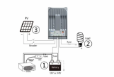
But the manual shows this
1596871274200.png

The 12V loads come off the SSC, I wasnt expecting that!! I cant find any specs for what load it can handle. I'm not planning on high loads but its just a bit unexpected

I cant quite work out why they have seperated off the inverter from the DC loads, after all isnt an inverter just another DC load? This is my current diagram, please dont judge me because its messy

1596872627590.png
 
The DC loads are run through the load port on the charge controller. It is limited in what it can power. It couldn't run the inverter.

You need to wire it like they did and treat them as completely separate circuits.

(3) don't see why they have two breakers - typically just on the (+) lead.
 
The DC loads are run through the load port on the charge controller. It is limited in what it can power. It couldn't run the inverter.

You need to wire it like they did and treat them as completely separate circuits.

I was looking at a video for the remote control display earlier. I see it shows load, does that mean it won't 'see' the inverter load?

(3) don't see why they have two breakers - typically just on the (+) lead.
I guess if they are seperately wired it needs to be seperately fused
 
(3) don't see why they have two breakers - typically just on the (+) lead.

Dual Pole breakers between Array and SCC is semi-common, don't ask me to explain why, I've tried to understand the logic and asked on the forum once or twice and so far haven't found a good explanation as to why or when to use a dual pole breaker.
 
I'm having a bit of a problem getting hold of some of the components I'd like and so I'm doing another diagram.

This time its the Epever Tracer BN 40A

I had it in my head that the battery connects to a couple of busbars and then everything connects to those including output from SSC, Inverter, and 12V distribution

But the manual shows this

View attachment 19364

The 12V loads come off the SSC, I wasnt expecting that!! I cant find any specs for what load it can handle. I'm not planning on high loads but its just a bit unexpected

I cant quite work out why they have seperated off the inverter from the DC loads, after all isnt an inverter just another DC load? This is my current diagram, please dont judge me because its messy

View attachment 19365
Typically, the small dc loads you want controlled by the charge controller are hooked to the load terminals. I don’t use them on my setups, other than for lighting he room the controller is in...

I wouldn’t hook those terminals to the bussbar, I would ignore them altogether.

I do like the dual pole breaker on the PV input.

So is there any disadvantage to doing this?

1596881869326.png

The advantage of this from my perspective is having one switch to throw to turn off all the loads
 
The only issue is some SCC track power out of the load port. You will not have any visibility of the DC loads unless you are using a separate shunt/battery monitor on the battery.

Other than that, it's great. I would do it the way you've proposed assuming you haven't made an error that I'm not seeing. I personally would add a breaker between the SCC and battery (+) to power off the SCC if necessary.

I'm not sure if I'm going to use the anderson style connector on the battery but that was partly the aim of having it there. I'll definitely put on on the solar. Much easier to be able to pull a plug apart to depower the system, especially with 90V

I havent goy my head round the DC breakers yet. Will look into it

1596904244469.png
 
Back
Top