diy solar

diy solar

Help me better understand Bypass Diode Function Please.

Nonlin

New Member
Joined
Oct 18, 2019
Messages
147
I think I get it but not sure.

Does a bypass diode activate once the PV cells in series produce voltage that is too low?

If so what is that threshold?
And if that treshold varies per panel how can I learn to read a spec sheet to understand that so I can get an idea for what shading is too much shading for a panel?

Because panels are supposed to still make power even partial shading but too much partial shading would kill all the PV cells in that series right?
 
Last edited:
I think I get it but not sure.

Does a bypass diode activate once the PV cells in series produce voltage that is too low?

Bypass diodes activate in response to MPPTs forcing a string voltage.

If a cell is shaded, then its output current at all voltages is going to be reduced. It's probably close to a linear response. By KCL (Kirchoff's current law) every cell in a series has the same current.

If you don't have bypass diodes then either the current will be choked, OR the current manages to pass through because photo cell has experienced some kind of breakdown event (these are bad and damage the photo cell. In fact preventing this breakdown is one of the reasons that bypass diodes must be added every N volts worth of cells).

If so what is that threshold?
And if that treshold varies per panel how can I learn to read a spec sheet to understand that so I can get an idea for what shading is too much shading for a panel?
Any shading is bad, and you can bet that there will be some time of the year where it's going to suffer the worst case. Anything above that the worst case is a boon from solar gods. There is no need to read a spec sheet. Well, besides learning what the internal layout is for, say, a half-cut format is so you are aware that there is a separate "blocking domain". Another type is shingled cell, which also gives alternate paths to bypass shading.

And (academically speaking) whether it's a weird panel type like CIGS that (IIRC) is chock full of bypass diodes.
 
And if that treshold varies per panel how can I learn to read a spec sheet to understand that so I can get an idea for what shading is too much shading for a panel?
It is variable.
Based on how much shading is placed on the cell string. And how much power is being produced by the rest of the series string.
When the cell string is shaded enough to be a load instead of productive. Power is bypassed around that string through the diode.
 
It is variable.
Based on how much shading is placed on the cell string. And how much power is being produced by the rest of the series string.
When the cell string is shaded enough to be a load instead of productive. Power is bypassed around that string through the diode.
Yes, and I'm trying to understand what is considered a load versus productive? Is there no way to actually find out or know based on your panel?
 
Yes, and I'm trying to understand what is considered a load versus productive? Is there no way to actually find out or no based on your panel?
No
Because it depends on how little the shaded cells are producing and how much the rest of the string is producing.
Both are constantly moving parameters.
 
No
Because it depends on how little the shaded cells are producing and how much the rest of the string is producing.
Both are constantly moving parameters.
Sure but isn't that just one factor for when it happens the other being how the diode is specked out/designed to work?
 
Sure but isn't that just one factor for when it happens the other being how the diode is specked out/designed to work?
It's just a simple diode, placed in parallel with the cell string.
Electricity will flow through the easiest path. The diode becomes the easier path, when the cells present resistance, instead of adding current.
The diode provides very little resistance.
It's a very simple design. I believe that you are over thinking it.
 
I'm not sure you can calculate how much shading is "ok" based on bypass diodes built into the panel.
In reality, any shade in the panel kills production. I had some panels leaning against the fence for a while. A weed grew up and shaded one cell on the bottom row, picking the week got me about a 30% boost. If your talking about shade from a tree or hard roof line, it will kill production.

Also, running current through the diodes makes them hot and can lead to failures.

The best plan is to mount the panels to avoid shading.
 
It is just current that causes bypass diode to activate.
Each photocell is a forward-biased diode, and bypass diodes are placed in reverse orientation every 24 or so cells.

When PV panel string is open-circuit, all cells and panels are at their open-circuit voltage.
Each cell produces current proportional to the amount of light it receives.

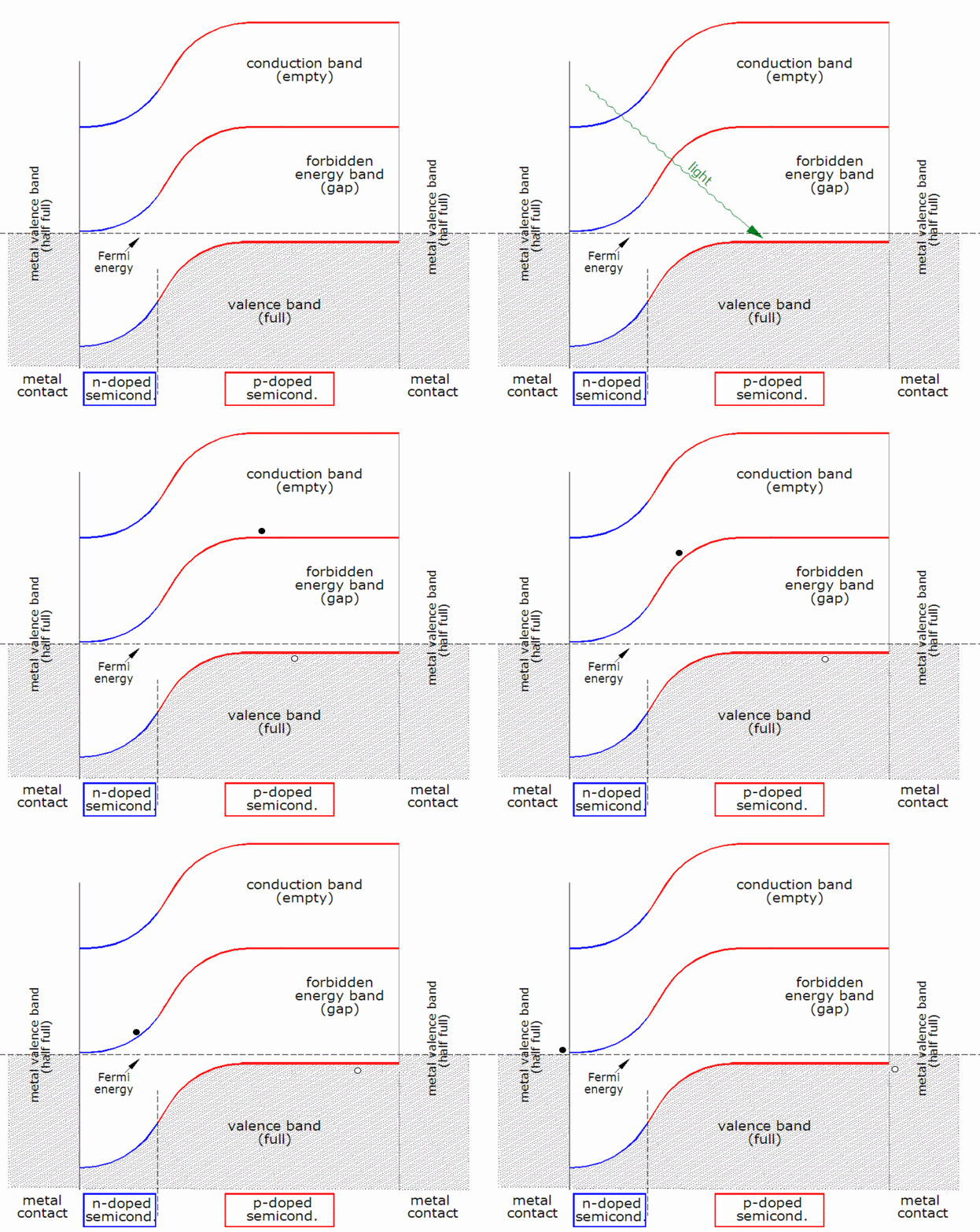
When open-circuit, voltage across the cell (a forward-biased diode) increases until current conduction through the cell equals the current produced (Voc). It is an exponential curve, so slight increase in voltage drastically increases the current. The voltage is approximately 0.7V per cell. (upper right quadrant)

1701097846254.png

If you put a load (such as a resistor) across the photocell, some current flows through the load, leaving less to flow back through the cell (diode), and voltage is reduced. At some load, this will be Vmp and current is Imp.

If you put a short across the cell (or PV panel), all current produced (Isc) flows through the short, none through the photocell, and voltage is zero.

Instead of a load, you can force current through the photocell (PV panel). If between 0A and Isc, the voltage will be between Voc and 0V. If you force more than Isc (or more than a partially shaded panel can produce), current would try to flow through the photodiode (lower left quadrant). At some voltage, high current flows and heating would damage the photocell.

That is where bypass diode comes in. At about 0.7V, the bypass diode carries all the current. Most PV panels have 3 diode bypassed sections, so 2.1V drop across the panel.

1701098707838.png

Problem is, bypass diodes get hot. At 10A x 0.7V, 7W per diode is dissipated. If not designed for sufficient cooling, the diode will overheat, short (but resistive short), burn the panel. Therefore, avoid shadows when panel is aimed directly at the sun. Probably fine at 45 degree angle from the side.


If a panel produces a bit less current than others, MPPT may let voltage rise and other panels deliver more voltage and a matching amount of current. If it produces substantially less current, MPPT should pull voltage lower and the high current of other panels is forced through its bypass diode. Whatever current the partially shaded panel produces also goes through its bypass diode.
 

We each rise to our level of incompetence. Mine lies somewhere below where quantum mechanics begins. Closer to Newton, with a bit of plumbing and check valves thrown in.

I designed state of the art microprocessors for Hewlett-Packard, having dropped out of a device physics class I was failing. But I knew Ohm's Law, and regarded a FET as a hose being pinched off. Worked for me!

 
Problem is, bypass diodes get hot. At 10A x 0.7V, 7W per diode is dissipated. If not designed for sufficient cooling, the diode will overheat, short (but resistive short), burn the panel. Therefore, avoid shadows when panel is aimed directly at the sun. Probably fine at 45 degree angle from the side.
Isn't fail-closed behavior on the bypass diode better for the panel? Because you will still get power from the other 2/3 plus prevent the shaded cells from going into breakdown and unaliving themselves.
 
I think fail-closed is likely (not enough power to blow them apart, like when I brushed a 3A diode across AC line.) But a melted blob of silicon has resistance, and may have higher voltage drop that the diode. Likely not significantly lower. So it could still overheat and crack the panel glass. We've seen pictures of melted and cracked panels, whether the diode failed or not I don't know.

A soft-start circuit I worked with had back to back FETs. It pumped up the gate slowly, and in the application the loads were not disabled until soft-start was complete. When the FET's blew, the melted one showed higher volage drop than the other, which still worked. Of course Vsat of a FET is usually lower than Vsat of a bipolar, which is lower than Vbe or voltage drop of any other diode.
 
It is just current that causes bypass diode to activate.
Each photocell is a forward-biased diode, and bypass diodes are placed in reverse orientation every 24 or so cells.

When PV panel string is open-circuit, all cells and panels are at their open-circuit voltage.
Each cell produces current proportional to the amount of light it receives.

When open-circuit, voltage across the cell (a forward-biased diode) increases until current conduction through the cell equals the current produced (Voc). It is an exponential curve, so slight increase in voltage drastically increases the current. The voltage is approximately 0.7V per cell. (upper right quadrant)

View attachment 179895

If you put a load (such as a resistor) across the photocell, some current flows through the load, leaving less to flow back through the cell (diode), and voltage is reduced. At some load, this will be Vmp and current is Imp.

If you put a short across the cell (or PV panel), all current produced (Isc) flows through the short, none through the photocell, and voltage is zero.

Instead of a load, you can force current through the photocell (PV panel). If between 0A and Isc, the voltage will be between Voc and 0V. If you force more than Isc (or more than a partially shaded panel can produce), current would try to flow through the photodiode (lower left quadrant). At some voltage, high current flows and heating would damage the photocell.

That is where bypass diode comes in. At about 0.7V, the bypass diode carries all the current. Most PV panels have 3 diode bypassed sections, so 2.1V drop across the panel.

View attachment 179897

Problem is, bypass diodes get hot. At 10A x 0.7V, 7W per diode is dissipated. If not designed for sufficient cooling, the diode will overheat, short (but resistive short), burn the panel. Therefore, avoid shadows when panel is aimed directly at the sun. Probably fine at 45 degree angle from the side.


If a panel produces a bit less current than others, MPPT may let voltage rise and other panels deliver more voltage and a matching amount of current. If it produces substantially less current, MPPT should pull voltage lower and the high current of other panels is forced through its bypass diode. Whatever current the partially shaded panel produces also goes through its bypass diode.
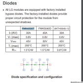
So for my panel it says it has FMK4530T Diode part, which I guess means I have to look at the spec sheet of that diode all I could find was this.
1701135824502.png


So my panel has 6x20 PV Cells, with three bypass diodes, meaning each bypass diodes should have 40 PV Cells in its string. My panel is rated at 41.25 VOC. So 41.25 / 3 = 13.75 / 40 = 0.34375 volts per PV Cell? If one cell is being shaded that would drop the volts from 13.75 to 13.4 which would not be enough to trigger a bypass, meaning that about 16.72 PV cells or rounded up 17 PV Cell would have to all be totally blocked before the bypass diode activates totally killing the entire string of all 20 PV Cells? Is that correct or am I missing something?

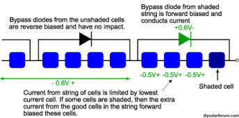
However this example/sim makes it seem like just blocking one cell should kill the whole panel?

Also how does MPPT play a role in all this?
 
Last edited:
You can ignore the diode specs for a couple layers of abstractions of understanding. Presumably the folks designing the module spec'ed the diode so it will somewhat live long enough for the expected amount of bypass the solar panel will see in its lifetime.

So my panel has 6x20 PV Cells, with three bypass diodes, meaning each bypass diodes should have 40 PV Cells in its string. My panel is rated at 41.25 VOC. So 41.25 / 3 = 13.75 / 40 = 0.34375 volts per PV Cell?

No, PV cells are in the 0.6ish V / cell range. What you are missing is that this is a half cut panel, which internally has 20s2p per 1/3. IE 20 cells in series, in parallel with another 20 cell series strings. These cells are half the size of full cut cells, which translates to same voltage but half the output current.

If one cell is being shaded that would drop the volts from 13.75 to 13.4 which would not be enough to trigger a bypass, meaning that about 16.72 PV cells or rounded up 17 PV Cell would have to all be totally blocked before the bypass diode activates totally killing the entire string of all 20 PV Cells? Is that correct or am I missing something? However this example/sim makes it seem like just blocking one cell should kill the whole panel?

You need to examine this in the CURRENT domain. The cells in a series string don't care what the other cells are at. It's the CURRENT that has to be consistent across the whole string (by KCL as mentioned upthread)

Also how does MPPT play a role in all this?

People usually talk about MPPT as if it is an adjustable operating voltage thing, but I wonder if adjustable operating CURRENT is a better way of looking at it. Either way, at a higher level of abstraction it finds the operating point corresponding to the global maximum power (which varies by current / voltage). If the charge controller / tracker only has a fixed operating point, then the power output could be significantly crippled.

Consider a PWM charge controller. It only has one operating voltage - the voltage of the battery - since PWM means that the solar string is alternatingly conducting / open. If there is a hard blocked cell in the string and the battery is above 2/3 of Voc/Vmpp then very little current will flow.

An MPPT has the appropriate DC - DC voltage conversion magic to isolate the voltage of the string from the load. Suppose we have a boost mode MPPT (this means it can increase the voltage relative to the input. somewhat rarer, but they exist. a lot of people on this forum just assume that MPPTs exist only in buck mode, but they're forgetting that there are millions of microinverters out there with 240VAC output vs ~40VDC input). Then in the same hard blocked case, the MPPT will operate at 2/3V_mpp, achieving 2/3 P_mpp. Thanks to the DC DC converter the output voltage will be boosted to the voltage of the battery.
 
120 PV cells? Probably not 40s for each diode, rather 20s2p. Are these half-cut?

If a single cell is shaded, it produces near zero current. If you short the PV panel, or even pull it down below 2/3 Voc, the other two sections without shade will push their current through the shaded section, and because that would reverse-bias the 20s of cells, voltage rises until the bypass diode activates.

Model is two sections of current source (PV strings) putting current through bypass diode, into load.
Or more accurately, each section is a current source (depending on illumination), parallel with 20 forwared-biased diodes. Pushing current through a bypass diode, and into the load.

You can test it with a resistive load. I used a couple space heaters in parallel.

MPPT is an SMPS, which switches to pump up current. By drawing more current, it lowers the voltage of PV panel (due to PV panel's I/V characteristics.)
The MPPT algorithm dithers back and forth, deciding which direction delivers the most power.
Some MPPT make periodic sweeps from zero current down, perhaps to minimum operating voltage, so find the highest peak. They they go back to dithering to track the peak.

However this example/sim makes it seem like just blocking one cell should kill the whole panel?

Which it would do, if no bypass diode as in the picture. That represents one diode-bypassed section.
 
Zany said / Hedges said.

Pick whichever wording you best follow.
 
Zany said / Hedges said.

Pick whichever wording you best follow.
I'm trying to code this into a sim with no real electrical background so what is being said is going over my head. I'm trying understand how it functions to see how I can simulate the effect to some extent even if as an approximation.

Currently my sim just says if a PV Cell is being shaded assume the watts it can produce is only 10% of what it would do.


But then learning about bypass diode made it seem like, no wait, if its blocked kill the entire watts from all the PV cells in its series.

But then it sounded like no wait, there is a threshold of drop that has to be met, etc...

Still piecing it together in my head.

ChatGPT hasn't helped me either it seems to be getting just as confused as I am lol.
 
Do you have an electrical simulator?
LTSpice is free and widely used.

The model for a PV cell is a current source in parallel with a forward-biased diode. Some resistance in there too. Make that a controlled current source, and you can vary illumination. Wire one cell's control separately for shading.


(As I said, the quantum goes over my head. Warped energy bands almost as much.)

 
I'm trying to code this into a sim with no real electrical background so what is being said is going over my head. I'm trying understand how it functions to see how I can simulate the effect to some extent even if as an approximation.
My last electrical class/homework was 20+ years before I had to dust it off for solar, so the EE required is not that hard. It did take staring at this stuff for 3 weeks and asking questions on the forum though.

How about this combinatorial-ish model:
  • Consider simulation in sections covered by bypass diode. The maximum current output of that section is (roughly) 1/3 Vmpp * min(cell level current, over all cells). The cell level current is the % shading I guess. I don't know how it translates physically nor do I really care for the purposes of understanding solar.
  • Now there are 8 possible combinations of bypass. For each combination, the global current will be the minimum of all non-bypassed sections. The voltage will be k * Vmpp/3, where k is the number of non-bypassed sections.
  • You can simulate the MPPT by taking the max() across all 8 scenarios
(Note one of those scenarios is really stupid because it corresponds to bypassing all 3 sections)

Once you understand that, you can move on to analyzing the different impact if it's a half-cut module.
 
Back
Top