diy solar

diy solar

Help me better understand Bypass Diode Function Please.

My last electrical class/homework was 20+ years before I had to dust it off for solar, so the EE required is not that hard. It did take staring at this stuff for 3 weeks and asking questions on the forum though.

How about this combinatorial-ish model:
  • Consider simulation in sections covered by bypass diode. The maximum current output of that section is (roughly) 1/3 Vmpp * min(cell level current, over all cells). The cell level current is the % shading I guess. I don't know how it translates physically nor do I really care for the purposes of understanding solar.
  • Now there are 8 possible combinations of bypass. For each combination, the global current will be the minimum of all non-bypassed sections. The voltage will be k * Vmpp/3, where k is the number of non-bypassed sections.
  • You can simulate the MPPT by taking the max() across all 8 scenarios
(Note one of those scenarios is really stupid because it corresponds to bypassing all 3 sections)

Once you understand that, you can move on to analyzing the different impact if it's a half-cut module.
Is this example accurate?
Lets say there are 72 cells, divided into three groups of 24 cells, with one bypass diode per group:
  • Each cell produces 0.6V, so each group of 24 cells produces 24 * 0.6V = 14.4V.
  • All three groups together normally produce 3 * 14.4V = 43.2V for the entire panel.
Now, if several cells in one group are shaded and the total voltage of that group drops, say, to 10V:
  • The total voltage for the other two unshaded groups remains 14.4V each.
  • Across the bypass diode for the shaded group, the potential difference is now the voltage of the unshaded groups minus the voltage of the shaded group.
  • This means the potential difference across the bypass diode is 14.4V (from an adjacent unshaded group) - 10V (from the shaded group) = 4.4V.
  • If this 4.4V exceeds the Vf of the bypass diode, the diode will become forward biased and conduct, allowing current to flow around the shaded group.
In such configurations, it's the voltage difference across the bypass diode, resulting from the lower voltage in the shaded group, that causes the diode to conduct, not the absolute voltage drop of a single cell. The diode conducts to protect the shaded group of cells and maintain current flow through the panel?
 
Now, if several cells in one group are shaded and the total voltage of that group drops, say, to 10V:
Think about the current being taken away, not the voltage!

How about this other way of thinking.

Suppose one cell is shaded to the extent where it reduces to 66% * I

If no bypass diodes are activated, you have 43V * 0.66 I

If bypass diode corresponding to that section is activated, you have (2/3 * 43) V * I

If the shading is 67% the MPPT will definitely pick operating at 43V (0.67 * I amps)

If the shading is 65% the MPPT will definitely pick operating at 28.6V (1.0 * I amps))

You can assume that activation corresponds to picking operation at 100% * I amps or 66% * I amps.

This of course is assuming a perfect MPPT that can distinguish between the two cases. And in actual scenario there will be some random diode drops biasing the voltages one way or the other.
What does it mean to have the MPPT pick? It doesn't get to decide if the diode activates and bypasses right? So how does it have a choice to pick an option where the Diode isn't bypassing?
 
I think this pdf is helping me make sense of things better. Assuming it's accurate.

MPPT can change enough aspects of the panel to change the outcome of power and it's all about the uniformity of the PV cells rather than strictly shading of any kind.
 

Attachments

  • se_technical_bypass_diode_effect_in_shading.pdf
    374.5 KB · Views: 10
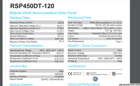
Also been looking at the wrong specs, these should be the correct for my testing/example but it doesn't directly say half cell for panel but I guess we can assume it is indirectly?1701182872052.png
 

Attachments

  • My panels Diode 40SQ045.pdf
    385.9 KB · Views: 1
You can tell if it has half-cells in parallel vs. full cells single string in series by counting the number of cells and comparing to panel voltage.

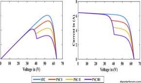
The MPPT SCC is a variable current source. It draws current from PV array, and voltage of the array/panels/cells decreases at higher current (or some funny shaped I/V curve, right graph.) All it does is draw current through an inductor and switch FET on/off with some duty ratio, which sets a particular current draw.

The job of MPPT is to find highest power peak on the W/V curve (left graph)

1701185004881.png

 
PV cells are illumination based current source, clamped in maximum voltage by its inherent, normally forward biased, diode.

Voc is no external load where any illumination generated current is just shunted down the cell's inherent diode.

Vmp is approximately 85% of Voc voltage where cell's inherent diode just starts conducting, shunting about 5% of illumination generated current down cell's inherent diode. This yields the highest Vcell x output current or MPPT point.

This voltage changes with PV cell temp, by about -0.026v per degC rise in temp for silicon cells (lower voltage for higher cell temp). Panels usually spec this temperature coefficient in % of panel voltage/degC because of differing number of series connected cells in a particular panel.

On a single cell basis, 0.026v/degC / 0.6v forward bias voltage for cell is about -0.4%/degC which is the approximate number you will see in the panel temp coefficient spec.

Isc is cell short-circuited current which is illumination generated current with cell held at near zero volts (short circuited) across cell.

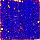
All PV cells have some parasitic shunt leakage resistance. Much of this shunt leakage resistance is due to silicon spot defects in PV cell substrate. These defects are spots of low resistance. They can vary in quantity and severity of resistance. Poorer quality cells have lower shunt leakage resistance with more spot defects. Lower shunt resistance degrades low light performance of PV panel where illumination current is low and a higher percentage of the lower illumination generated current is bled down shunt resistance.

A panel voltage will jump to Voc in the morning as soon as the illumination current rises above the leakage current of panel. At the point the panel illumination just overcomes the panel leakage current, and jumps to Voc, the panel will still not support any external load. The rising Voc may cause charge controller to wake up but as soon as it tries to load panel, the panel voltage just collapses shutting the charge controller down again, until the sun rises enough to provide more illumination current.

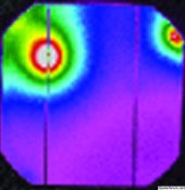
The low resistance spot defects are what the bypass diodes are for. They protect the cell from hot spots developing due to high reverse biasing of cell during shading. Without bypass diode the defect spots may get very hot under partial panel shading condition due to high reverse bias voltage.

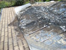
In unshaded normal conditions, each diode is forward biased with about 0.5 to 0.7vdc maximum voltage across cell. When cells are connected in series and panel is loaded, a shaded cell will be driven into high reverse bias voltage from the other unshaded series connected cells without a protective bypass diode. While at 0.5-0.7 vdc normal conditions the shunt defect does not dissipate much power, but when a high reverse bias voltage happens, a defect shunt resistance spot can get very hot. This can damage panel, or in worse case, start a fire.

Bypass diodes are usually placed in parallel with a group of 16 to 22 series connected cells, across an up and back cell row pair in panel to make connection to bypass diode in junction box at one side of panel. Typically, one bypass diode spans no greater than 16 to 22 cells in the two-row pair, so the maximum reverse bias on any single shaded cell is limited to 8 to 12 vdc.

Hot spot PV cell.jpg Color image of PV cell defects.jpg

Panel defect fire.jpg
-
 
Last edited:
Back
Top