diy solar

diy solar

Help me understand my solar charge controllers

mystic pizza

New Member
Joined
Jun 20, 2021
Messages
134
Further to my last post, I am not sure I understand how my controller(s) actually work, or if they are not working as they should.

I wonder if someone could explain please.

To test the system, I have the boost set at 13.9V, the float set at 13.9V, and the boost reconnect set at 13.8V, with a boost duration of 45m.

Charge controllers are 12 V Outback flexmax 30s feeding a LA/lithium hybrid system.

I have been expecting the absorption/boost voltage to reach 13.9 V, hold for 45m then drop to a float charge, with zero current.

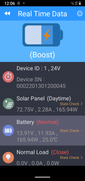
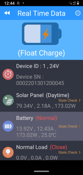
What appears to happen is that the controller reaches the boost voltage of 13.9 (whilst the battery voltage remains at 13.5V) and then drops into float, but continues to supply current at the same rate as in boost mode.

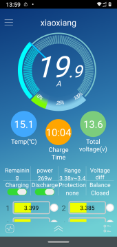
The first two images are data from one of the charge controllers. The second image is from the Lithium BMS.
Thanks
 

Attachments

  • Screenshot_20220411-120627.png
    Screenshot_20220411-120627.png
    193.9 KB · Views: 3
  • Screenshot_20220411-124433.png
    Screenshot_20220411-124433.png
    196.9 KB · Views: 3
  • Screenshot_20220411-135951.png
    Screenshot_20220411-135951.png
    505.4 KB · Views: 3
I am not sure of your exact build but if you have lead acid in parallel, when you cut off boost to a lead acid, it will settle at a lower voltage, typically under 13v. Your changer would then try to float that battery at 13.9v, which could cause at least some current to continue to flow.
 
The battery pack determines how much current it will take, not the controller. With 13.9 volts charge and the same 13.9 volts float no change in current taken by the battery is expected until the battery pack nears full charge.
Without knowing the battery capacity, tail current cannot be suggested.
It seems there are volt drops in the connectors between charger and battery.

Mike
Do you mean because the BMS is reading lower than the controller? Its a 280Ah lithium bank in parallel with a nominal 440 Ahr LA bank (probably less than this now).

I don't think the battery is anywhere near fully charged, and that kinda is backed up by the BMS reading.
 
I am not sure of your exact build but if you have lead acid in parallel, when you cut off boost to a lead acid, it will settle at a lower voltage, typically under 13v. Your changer would then try to float that battery at 13.9v, which could cause at least some current to continue to flow.
That is true, but if the LA is fully charged, I would not expect so much current to flow?
 
That is true, but if the LA is fully charged, I would not expect so much current to flow?
If you have a DC amp clamp on meter, check your lead acid battery cable and see what is happening. I wouldn't guess. I think once charged lead acid just tend turn charging current into heat and/or gas, so I wouldn't guess on what that current would be. If you set your Float on something for lead acid, you might see something more normal. Is that lithium LiFePo4? You might try Float at 13.0v and see what happens. That would cause a little discharge of the LiFePo4 before Float kicked in. Then set Boost reconnect somewhat lower like, 12.4-12.5v range.
 
Ok, just measured the current into the LA with a clamp meter. Approx 1A. Yes, they are Lifep04's with a bit of yttrium in.
 
Back
Top