diy solar

diy solar

Help needed choosing MPPT charge controller

OK, the Vmp is just doable but you will need to use a Victron or better. The epevers and other cheaper controllers all have too high a voltage difference requirement to be able to keep the panels at Vmp sucessfully. Some of them won't even go into MPPT mode with voltages as low as this instead staying in a pseudo-PWM mode.

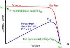
Even Victron will be at the limits in terms of voltage. Victron needs 5V over to commence charging, so you get away with it there with 22.32V Voc and 1V over to continue charging and again you just scrape in with 18.1V.
I’d like to clarify something @gnubie - when you said “and 1V over to continue charging and again you just scrape in with 18.1V. “ what did you mean? 1V over what?
 
1V over battery voltage. At 18.1V Vmp you are flying really close to the point where the array Vmp is actually below the present battery voltage (thermal derate etc). Depending on the charger it may decide to stop charging outright but it may also head to the right side of Vmp to keep the voltage above battery so that it can charge. There's a steep price for doing that though as the current available quickly falls off. Once you are into this territory you really want a PWM charger, or at least a MPPT charger that has a pseudo-PWM mode.

Victron is one of the lower minimum differences, epever requires 2 volts over. If you had mono panels you'd get more margin but it'd still be pretty low.

1602826866981.png
 
1V over battery voltage. At 18.1V Vmp you are flying really close to the point where the array Vmp is actually below the present battery voltage (thermal derate etc). Depending on the charger it may decide to stop charging outright but it may also head to the right side of Vmp to keep the voltage above battery so that it can charge. There's a steep price for doing that though as the current available quickly falls off. Once you are into this territory you really want a PWM charger, or at least a MPPT charger that has a pseudo-PWM mode.

Victron is one of the lower minimum differences, epever requires 2 volts over. If you had mono panels you'd get more margin but it'd still be pretty low.

View attachment 25144
Thanks @gnubie, it’s clearer now and I do appreciate your advice. In the near future (next six months let’s say), thermal de-rate shouldn’t be too much of a worry as here in Sweden temps are plummeting. It just about made it to 10C today, but pretty soon positive temps will be just a wistful memory and -20C a definite possibility.

I’m wondering if it might be only during May - Aug (when we might see 30C on the hottest days) that the MPPT marginal conditions you mention could become a concern.

So my proposed solution right now is to buy a Renogy Rover 20 Li mppt controller and put it to work so I liberate some more power from my 2 x 160W parallel connected panels. At just €26 for a Renogy Wanderer 30A lithium compatible PWM controller, I have no problem buying one just for use during the summer should the MPPT controller begin to struggle when the panels are hotter. Swapping between the two shouldn’t take much time or trouble. Both the Rover and wanderer are compatible with the BT-1 bluetooth module and Renogy mobile app, so swapping between them won’t affect my user interface for system monitoring.

I do accept the points made earlier in the thread that PWM is not necessarily less efficient in all situations, but there are two factors specific to my installation mean MPPT should have advantages. The first is the somewhat long 16m cable run (32m circuit length) between panels and charge controller. Higher voltage, lower current MPPT should reduce my cabling power losses. The second issue is my existing cheapy cheap PWM controller makes the pipes in my house “sing“ when it’s in the throttling phase, so with MPPT I should be able to cut that out. And yes, I’ve used my domestic pipework as busbars to get my panel current from attic to downstairs (and no, they’re not gas pipes, don’t worry ;)?)
 
The second issue is my existing cheapy cheap PWM controller makes the pipes in my house “sing“ when it’s in the throttling phase, so with MPPT I should be able to cut that out. And yes, I’ve used my domestic pipework as busbars to get my panel current from attic to downstairs (and no, they’re not gas pipes, don’t worry ;)?)
You are using your pipes as wire from the panels to the charge controller? I have never heard of such a thing in my 13 years in the industry. Conduit as ground yes, pipes as wire, no.
 
You are using your pipes as wire from the panels to the charge controller? I have never heard of such a thing in my 13 years in the industry. Conduit as ground yes, pipes as wire, no.
I’m pleased to be able to introduce a new idea to the industry ? Maybe I should have filed the patent before posting though?

In fact only the positive volts are travelling through a 1” copper pipe which transits right through the whole height of the house from the utility room where the charge controller is, up to the attic space. The other conductor (for the negative side of the circuit) is the ventilation air duct which has a grille in the utility room and which by happy coincidence passes via the attic space. I suspect this is the one which sings when the PWM controller throttles, as it is probably steel and thus gets some electromagnetic excitation from the current passing though at PWM frequency.

A tiny hole, a washer soldered to the end of the wire and a self tapping screw suffice to make a sound electrical connection which works up to the 16A or so I’ve been able to test with so far. I’ve checked the connection points for any warmth which might indicate a high resistance connection and they appear sound to me.

You won’t find it in the industry best practice handbook or the electrical code, but gained me an extra 8m or so of cable run for free, with less DC resistance per metre than the 4mm cable I’ve run for the rest of the length.
 
Last edited:
With low temperature voltage rise you likely will be OK to use a MPPT controller. Since it gets very cold in your location make sure your Voc does not exceed what ever the rating of the MPPT controller you use at -20 (my wall thermometer doesn't even go that low). That'll only be a concern if you use a really low end controller.
 
With low temperature voltage rise you likely will be OK to use a MPPT controller. Since it gets very cold in your location make sure your Voc does not exceed what ever the rating of the MPPT controller you use at -20 (my wall thermometer doesn't even go that low). That'll only be a concern if you use a really low end controller.
Thanks @gnubie - the Renogy Rover allows up to 100V DC at input, so I think that’s plenty safe.

-28C is the lowest I’ve seen here, but that was at night, so no sun ?
 
Here in Sweden at nearly 60 degrees latitude we get fantastic long, sunny days in summer, but now we are heading into winter where the reverse is true. So short days and often cloudy. I was thinking MPPT might help salvage more power during this coming season during the overcast conditions, but if there are solid reasons to stick with PWM then I will do so.
What is the purpose of your solar installation? Are you off grid?
On overcast winter days expect no more than 5% from your panels and that just for a few hours, so you get hardly a positive balance.
The own consumption of the SCC will prevail, and every fancy WiFi gadget draws energy...

You might want to check here European Solar Calculator what you can hope to get in winter, mainly peanuts...

Additionally the "fantastic long, sunny days in summer" come together with a sun turning wide over 180° so you will probably need to have two panel orientations at least, if you want to get the max of that conditions.
 
-28C is the lowest I’ve seen here, but that was at night, so no sun ?

I believe the problem is precisely at sunrise when the voltage goes high before the panels warm up.

That’s when I typically see the highest voltage of the day when it’s cold out.
 
I’m pleased to be able to introduce a new idea to the industry ? Maybe I should have filed the patent before posting though?

In fact only the positive volts are travelling through a 1” copper pipe which transits right through the whole height of the house from the utility room where the charge controller is, up to the attic space. The other conductor (for the negative side of the circuit) is the ventilation air duct which has a grille in the utility room and which by happy coincidence passes via the attic space. I suspect this is the one which sings when the PWM controller throttles, as it is probably steel and thus gets some electromagnetic excitation from the current passing though at PWM frequency.

A tiny hole, a washer soldered to the end of the wire and a self tapping screw suffice to make a sound electrical connection which works up to the 16A or so I’ve been able to test with so far. I’ve checked the connection points for any warmth which might indicate a high resistance connection and they appear sound to me.

You won’t find it in the industry best practice handbook or the electrical code, but gained me an extra 8m or so of cable run for free, with less DC resistance per metre than the 4mm cable I’ve run for the rest of the length.
May I suggest,

1) AFCI, so if poor contact begins arcing at ductwork joints, it turns off the circuit before igniting the walls? (Won't help in the case of just a dull red glow; needs the AC signature of an arc.)

2) GFIC, so if some poor soul has one hand on the faucet and uses the other to touch a vent, the circuit he completes is interrupted after a few milliseconds? What voltage, by the way?

We commonly have our water pipes, gas pipes, and earth ground tied together for electrical safety. Then we put a dielectric union between copper and steel water pipes to avoid corrosion, but we also electrically bond across the dielectric union for the previous electrical safety reason. I think it is supposed to still do some good if the path to electrolyte (water) between dissimilar metals is somewhat long.

Electrical bias of pipes or steel under ground is a technique used to prevent corrosion, with proper polarity and low voltage but sufficient current to reverse polarity created by electrochemical action. Simpler passive methods are also used (galvanization, sacrificial anodes on boats), but structures like bridges will have a voltage imposed.

Your charge controller might object to one of PV inputs being arbitrarily grounded, if your pipes are grounded. If they aren't grounded but charge controller (and perhaps inverter) ground negative in some way, then some one in the show standing on a grounded pan and touching shower head/faucet could be at risk. We'll keep an eye out for your obituary and epitaph. :)
 
I believe the problem is precisely at sunrise when the voltage goes high before the panels warm up.

That’s when I typically see the highest voltage of the day when it’s cold out.
What voltage increase do you observe in such circumstances, and when you say cold, what kind of temps?
 
When it’s super cold around here we never get much snow. YMMV
I’m hoping the 60 degree inclination of my panels, due to the low height of the winter sun will be enough to allow snow to fall off - but time will tell on that one.
 
May I suggest,

1) AFCI, so if poor contact begins arcing at ductwork joints, it turns off the circuit before igniting the walls? (Won't help in the case of just a dull red glow; needs the AC signature of an arc.)

2) GFIC, so if some poor soul has one hand on the faucet and uses the other to touch a vent, the circuit he completes is interrupted after a few milliseconds? What voltage, by the way?

We commonly have our water pipes, gas pipes, and earth ground tied together for electrical safety. Then we put a dielectric union between copper and steel water pipes to avoid corrosion, but we also electrically bond across the dielectric union for the previous electrical safety reason. I think it is supposed to still do some good if the path to electrolyte (water) between dissimilar metals is somewhat long.

Electrical bias of pipes or steel under ground is a technique used to prevent corrosion, with proper polarity and low voltage but sufficient current to reverse polarity created by electrochemical action. Simpler passive methods are also used (galvanization, sacrificial anodes on boats), but structures like bridges will have a voltage imposed.

Your charge controller might object to one of PV inputs being arbitrarily grounded, if your pipes are grounded. If they aren't grounded but charge controller (and perhaps inverter) ground negative in some way, then some one in the show standing on a grounded pan and touching shower head/faucet could be at risk. We'll keep an eye out for your obituary and epitaph. :)
Thanks for your suggestions!

1) It may be a sensible precaution, but I would be surprised if a pair of 22 Voc panels, wired in parallel cause arcing however bad their electrical connection to the pipe or duct is. There are, in any case, dual redundant connections at each end of the circuit (attic and utility room), so two cables which are parallel connected at their far ends (source and destination) have independent insert & exit points to the pipe and duct. This means that even if one has a bad electrical connection, there is no potential difference between it and the metalwork (save for a few millivolts) due to the alternative current route via the second cable. This is a fortunate side benefit of the fact I’ve run two cables to lower the DC resistance and reduce cable power loss.

2) Someone with their hand on the faucet has no connection to any part of my off grid circuit, so that’s irrelevant. The pipe I’ve used as a busbar is a disused one which used to serve a header expansion tank connected to a long-since decommissioned boiler which was in the utility room. In any case, the system runs at 12-18V DC, so nothing which will pose a risk to anyone who manages to connect themselves in circuit.

There is no ground connection via the pipe or charge controller and no inverter in the system. If it will please you, I’ll reserve some space for the obit in ”Solar Misadventures Monthly”, but can’t see myself needing to use it. ?
 
What is the purpose of your solar installation? Are you off grid?
On overcast winter days expect no more than 5% from your panels and that just for a few hours, so you get hardly a positive balance.
The own consumption of the SCC will prevail, and every fancy WiFi gadget draws energy...

You might want to check here European Solar Calculator what you can hope to get in winter, mainly peanuts...

Additionally the "fantastic long, sunny days in summer" come together with a sun turning wide over 180° so you will probably need to have two panel orientations at least, if you want to get the max of that conditions.
Sorry, missed your reply earlier when I replied to others who’d posted after you.

Thanks for your tips. I’ve already experienced a run of heavily overcast days and was dismayed by how little the panel produced - its what lead me to order a second identical 160W panel to run in parallel, but even so I’m quite sure there will be plenty of days thru the winter when I run out of power and need to switch on a mains powered battery charger.

The purpose of my solar exploits has been something of a moving target. I suppose where I’m at right now is that it will reduce our mains power bills as I transition as many household devices from inefficient “wall wart” PSUs to running direct from solar DC.

The initial aspiration when I first began looking into solar was “how do I run my house ventilation fan on solar power, can I just stick a 20W panel straight on the top of it and have a battery local to the fan”. I decided that wasn’t viable and it would be better to get a larger 160W panel to charge a car battery to run the fan plus whatever other devices the available power would stretch to.

So what started as “small solar panel connected direct to one device” turned into ”bigger panel charging a car battery” and that has now evolved into two solar panels, an MPPT controller and a 100A LiFePO4 battery. The costs seem to go ever upwards once you get sucked into this solar panel lark!
 
When it’s super cold around here we never get much snow. YMMV
[edit] I have just seen that you answered meanwhile.

But you didn't answer my question:

What is your usage of the installation?
Are you off-grid or not? Do you NEED energy in the wintertime?
Have you got an usage of the energy that does not fit into your battery during summertime?

That are the key questions governing the overall design.
Yes, I think I answered these in my other comment from a short time ago, except the last point. In summer I would expect to have an excess of power to use and will likely have an inverter by then to run some mains devices such as fridge and freezer, outdoor lighting overnight, maybe TV if there’s really plenty of excess. Basically my strategy will be to scale demand to match the solar energy supply, as I can switch plenty of devices in the home between mains or solar.

I’ll only be using an inverter for devices which won’t run DC and will use low power DC/DC buck/boost voltage converters to drop down to 9V, 5V etc as needed.
 
Back
Top