diy solar

diy solar

HELP NEEDED: If you have a ~1KW or less, Solar System w/ Lithium Iron Phosphate Batteries

Michael77

New Member
Joined
Aug 24, 2022
Messages
91
HEADER: FOR DATA GATHERING PURPOSES, PLEASE LIMIT THE COMMENTS IF YOU DO NOT HAVE THE REQUESTED INFORMATION – THIS WILL HELP THE PROCESS OF GATHERING REAL WORLD DATA – THANK YOU

If you feel like commenting on this post, please at the top of your comment state: I Do Not Have Qualifying Data – this way we can see who has hard data and who is just making comments – thanks

Hi. Thank you for your help, I am trying to get some real world data from users with Lithium Iron Phosphate Batteries, and Small to Mid Sized Solar Panel Systems

The most important thing is that: You have Lithium Iron Phosphate Batteries, NOT Lead Acid. Also, it is important that you do not have hardware that is using communication connections in use during requested measurements – if you do have nice hardware with communication connections, and you would still like to contribute, it would be great if you could take measurements with data sharing on, and off, if possible, but not necessary, just make sure to mention the data sharing.

Requested: AT PEAK SUN; preferably, with no load on the system, AND with 40/70% Battery State Of Charge

* Please measure your Solar Charge Controllers Voltage in App (If available) and at the Terminals

* Please measure your Batteries Voltage in App (If available) and at the Terminals

That is all. If you would like to give detailed information about your configuration starting with

1. Panel Size & Specs
2. Charge Controller Specs
3. Battery Size & Specs
4 Cable Length & Thickness
5. Average daily usage details, i.e. heavy usage, or always charged up

Again, At Peak Sun, with a relatively discharged battery, very important that you get the readings mid day in good sun, and preferably with no load, or very little load, take the terminal and app readings for your Charge Controller and Battery and post them – that is the most critical data needed to build a real world database. Pictures from the Apps, and the actual readings would be greatly assistive as well.

Thank you for your help.

(Hate to reiterate this, but; Please do not make comments, looking for real world data, not a contest, right, wrong, theoretical, bad, good, nice, beautiful, shameful commentary. Just the facts, thanks)
 
Last edited:
I will be the first to share my values

Charge Controller:
In App & at Terminals - 14.44v Img 1 & 2

Battery:
In App 3.4v - At Busbars, closest to terminals I could get & before the BMS: 13.51v Img 3 & 4


1. Panel Size & Specs
6x100w Solar Panels Parallel

2. Charge Controller Specs
40Amp MPPT Charge Controller

3. Battery Size & Specs
Main Battery, the only one connected during these tests is 280Ah LFP

4 Cable Length & Thickness
Standard Parallel Adapters at the panels, connecting to 2 sets of 10AWG Solar Panel Extension Cables
Between the Charge Controller & Battery/Busbars is a 3foot, 8 AWG Thin Strand Silicon Cable w/ T90 Connector.
250Amp Busbars, 2 foot 2 AWG Cable to Battery

5. Average daily usage details, i.e. heavy usage, or always charged up
I use my system daily, heavy loads, charging and discharging between 40% and 80% SOC daily. I also have a second battery that I parallel in the system for extra capacity. My system is still evolving, Measurements were done with the single battery because second battery does not have Bluetooth App, or any way to read the Battery BMS.

I hope that is the information you are looking for, it really wasn't hard to gather this data, it literally took me 5 minutes to make the measurements. Its hot out there, stay cool!
 

Attachments

  • Img1.jpg
    Img1.jpg
    118.8 KB · Views: 6
  • Img2.jpg
    Img2.jpg
    101.3 KB · Views: 6
  • Img3.jpg
    Img3.jpg
    229.9 KB · Views: 5
  • Img4.jpg
    Img4.jpg
    133.5 KB · Views: 6
Last edited:
( I HAVE QUALIFYING DATA )

In reply to the last episode: Well thank you for the information, I still think that LFP Lead Acid Drop In Replacement batteries are safe to use with non-programmable PWM Charge Controllers, Simple wall chargers, and other 12v charging equipment, including "dumb" equipment designed for Lead Acid Batteries, where the BMS stops the charge cycle. I highly recommend you reach out to the Manufacturers on this matter and get their official stance on this, because there is currently conflicting information being presented by several reviewers/sales reps. I have reached out to the Manufacturer of my BMS and am waiting for a reply. (It is Sunday, and I hope to have a response soon, will post the response when I get it.)

I ran my battery for years with the only way for the charge cycle to be halted was for the BMS to stop the charge cycle. And I was using a Renogy Wanderer LFP Version, that you recommended, and got a commision on. This is a non-programmable Solar Charge Controller that is designed to work with LFP, and the ONLY way the charge cycle was stopped is when my battery's BMS stopped the charge cycle. And it worked great for two years, thank you very much. And the new MPPT Charger I am using behaves the exact same way, there is no way for me to program the Charger to stop the charge cycle. Again, I have to rely on the Battery BMS to stop charging. I do this daily and it works great.

And I, in principle I agree with your Statement: "Charge controller absorption voltage should always be lower than BMS HVD threshold." This still doesn't invalidate the parameter of having the BMS stop the charge cycle. You are stating that: "Charge controller absorption voltage should always be lower than BMS HVD threshold" And, so yes, fine. But the BMS can still stop the charge cycle, and new modern Batteries and BMSs are designed as "LFP Lead Acid Drop In Replacements" - specifically; "If you are using any charger that is 14.4 or 14.6 you can charge this battery with no issues, you do not need a Lithium specific charger or special Lithium Charge Controller." The sentiment of that statement is that the BMS will stop the charge cycle. This very point is industry standard for all modern LFP Drop In Replacements. The BMS is designed to stop the Charge Cycle, this is a blanket statement - this does not cover out of spec settings. Agreed.

Cringy crimp did have electrical tape on it, but yea, it's a cringy crimp, though it is safe, and within spec. Grammar & Punctuation notwithstanding, thank you for your personal jab into my typing and communication skills, COVID did mess up my brain slightly, and I have noticed that when I am typing a long text, sometimes I forget to use conjunctions, or I use have instead of has, etc before I proofread, and after I post, and reread what I just said, I see things that my brain was trying to say, but my clickity click typing fingers somehow managed to omit, or in some cases, use an entirely incorrect word!? So, yes, but overall the concept and message is conveyed. And for Some Reason, Every other Word has to be Capitalized! lol

"Charge controller absorption voltage should always be lower than BMS HVD threshold." Again, conforming to Standard Industry Parameters, I agree with this, BUT; in my post regarding using "Higher Allowable Voltage Limits" to get the most out of your Solar System, I do crank up the voltages beyond Industry Standard. I explain my configuration, I outline and qualify the setup, the details about the battery and my MPPT Controller, I discuss the issues I was running into and I present my solution. And by using the BMS to stop the charge cycle, instead of the MPPT Charge Controller throttling down half way through the charge and not giving all available amps all the time - because of its logic, designed to be overly cautious, and to throttle down towards the end of the charge cycle, and to NEVER go above the Industry Standard HVD Threshold, the Charge Controller was literally tripping over itself and throttling, only giving me ~20 Amps out of the available 30 Amps. I cranked up the allowable voltages, turning off the Boot Timer, and fully opening up the "Allowable Voltages" to 15.2v. The Controller never actually achieves those high voltages, and under load it is usually in the low 14s, 14.0/2/4 etc. And most importantly, it doesn't trip over itself and throttle, it allows all available current all the time. I rely on my BMS to not only stop the charge cycle, but to also do all those other things it's designed to do like: Over Current, Over Voltage, Reverse Polarity, Low Voltage Disconnect, etc... And I explicitly state repeatedly in my post: MY BMS WORKS. (And we are talking about sub 40A charging rates, well below the industry acceptable 50/100 Amp Current Rating, as state in the post)

Okay. I originally set the settings to 14.8/14.8/14.8 & 14.7. I guess you could call this the tippy top limit of what is allowable as "Industry Standard" - and at these settings the MPPT Controller did not trip over itself or throttle, but I threw caution to the wind and said: "(After extensive research, I ended up bumping the settings from 14.8 to 15.2/15.2/15.2/15.0 - but I did not see any increase in Amps, but based on my research I decided 15.2 would be plenty safe, and my actual charge controller would never be able to hit that voltage anyway, and if it did, at peak peak peak for a brief second, it would only be for a brief second... and would be totally safe...)"


I will now retract that move to higher controller limits because: Good News Everybody! I have the results of the Wire Upgrade!

I will now drop down from 15.2/15.0, back to 14.8/14.7 and I will still use my BMS to stop the charge cycle. (EDIT: My BMS High Voltage Disconnect is 14.55) And, even with the crappy (should be banned from import) wire, I was NEVER able to hit voltages higher than 14.8...

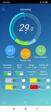
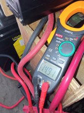
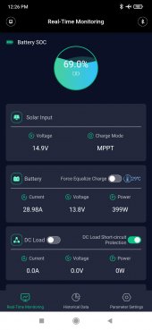
First Image is of the Battery BMS App Voltage: 13.4v (31 Amps Baybe! Highest Average Amps Seen. Old Wire WAS CRAP!)
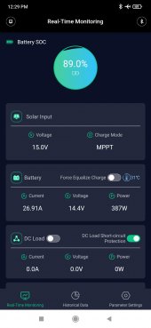
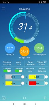
Second Image is of the Charge Controller App Voltage: 13.8v - Still a large delta, but much better.
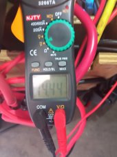
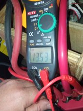
Third Image is the Battery Voltage at the Busbar/closest to "Terminals I could get: 13.53v
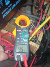
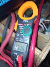
Fourth Image is the Charge Controller Voltage at the Terminals: 13.75v
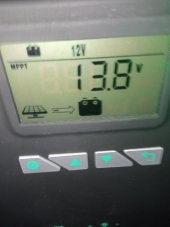
Fifth Image is the MPPT Screen Reading: 13.8v
Sixth Image is PV Input Voltage at Charge Controller Terminals: 14.91v
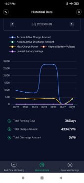
Seventh Image is the Daily Historical Data, there is a dip at the beginning of the week that is not real. The real numbers daily are ~2,000/3000 WH Daily as seen in the last few days of the data set.
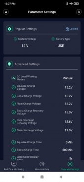
Eighth Image is how my MPPT is currently configured, and as I said I will drop them to 14.8/14.7v

There is still a higher than expected, delta from the Charge Controller to the Battery. People in this forum have stated that any delta higher than a .5v deviation is bad. I completely disagree.

Literally, the title of this thread is "Your Charge Controller "Charges" the line between your Battery." (That Thread is locked)

I still stand by my assertion, and theory aside, I have now asked for other people to provide real world data. I have provided my setup, configuration and all relevant data, with included pictures. I am asking others to do the same, can you help with this. My system configuration is in the post below (or above?), you have the equipment and knowhow to run the real world test. And based on how many people insisted on chiming in on this conversation, there should be at least several other people with comparable hardware who can take measurements of their own system, and show that what they are saying exactly how their own system works. As it stands not a single person has bothered to show their measurements.

No one is willing to put the work in to get real world data to back up the claim that: "The ONLY difference you should have between the OUTPUT terminals of the charge controller and the BATTERY terminals would be the voltage drop (resistance) of the cable connecting the two. If that drop (resistance) is too high, there IS something wrong with your system."

And that is why I am basically saying; PROVE IT - I showed you my system, now you show me yours. My VERY point is that, you too, will see more Voltage Delta than just the resistance of the wire. As is clearly shown in my case. Yes the wire was bad, but even with the new High Quality 8AWG Thin Strand Tinned Silicon Cable, I am still seeing a Voltage Delta that would be considered too high. I believe this is normal. Prove me wrong by running the same tests on a comparably configured system as outlined above.
 

Attachments

  • 8-28Img007.jpg
    8-28Img007.jpg
    120.3 KB · Views: 2
  • 8-28Img006.jpg
    8-28Img006.jpg
    144.5 KB · Views: 2
  • 8-28Img005.jpg
    8-28Img005.jpg
    74.1 KB · Views: 2
  • 8-28Img004.jpg
    8-28Img004.jpg
    113.9 KB · Views: 2
  • 8-28Img003.jpg
    8-28Img003.jpg
    124 KB · Views: 2
  • 8-28Img002.jpg
    8-28Img002.jpg
    119.5 KB · Views: 2
  • 8-28Img001.jpg
    8-28Img001.jpg
    229.1 KB · Views: 1
  • 8-28Img008.jpg
    8-28Img008.jpg
    123.2 KB · Views: 1
Last edited:
Drop in replacement batteries have to be designed for that market and their warranty and the price includes the chance that the BMS might give up the ghost or a cell could go bad. Who knows but they also may use lower limits.
As you have discovered from users like me who have systems larger that one kWh the investment in the pack becomes significant and the risk management strategy is going to be different for a $10,000 investment in batteries is going to be different than for a $50 rechargeable device that is charged with a wall wart.
 
And that is why I am basically saying; PROVE IT -
I don't need to prove anything beside what I have already said and which has been reiterated many times by other knowledgeable people including Will Prowse. I gave you my qualifying data but it was for a 42 kWh system and clearly not relevant to your world of wall warts and drop in replacements. Most of the users hear are building bigger systems.

Also with regard to the question about how to set up a charger and a BMS to manage a pack, clearly there is a consensus of opinion that the first line of defense should be the settings on the charger. The only reason I continue to respond to your posts is not to argue with you or change your mind. My purpose is so that other readers will see another viewpoint and be able to form their own opinion. You are free to live in a world of wall warts and drop in replacements and do it your way.

I prefer to spend my money differently and take the knowledge I have gained from my experiences on sites like this and follow a different course of action. This all boils down to beliefs and beliefs sometimes get confused with facts and options but it is up to you to find the course of action that works for you. I do have to compliment you for your willingness to own up to the sloppy connections you made in the first place. They reminded me of the first Heathkit I built in 1957 when I first learned Ohms Law. My knowledge has scaled up since my first E bike conversion in 2010 and so has my investment in battery from the first 1500 Watthour pack, to my current 42 kWh pack at my home and the 150 kWhs of batteries in my two Teslas.
 
Last edited:
Drop in replacement batteries have to be designed for that market and their warranty and the price includes the chance that the BMS might give up the ghost or a cell could go bad. Who knows but they also may use lower limits.
As you have discovered from users like me who have systems larger that one kWh the investment in the pack becomes significant and the risk management strategy is going to be different for a $10,000 investment in batteries is going to be different than for a $50 rechargeable device that is charged with a wall wart.
Okay. Thank you. I would rather not fill this thread with a conversation about this, because it would be nice if it was just filled with user system configurations and measurements, but I see what you are saying and agree. It's not a perfect world. That said, I do recommend you take a look at this video. The warranty is 5 years, and this guy HAMMERS the battery. It's a good watch, just 2X the playback speed. As a representative of the Manufacturer he states "If you are using any charger that is 14.4 or 14.6 you can charge this battery with no issues, you do not need a Lithium specific charger or special Lithium Charge Controller." Anyway. Thank you. Peace

(If you would like to continue this conversation, post in the other crazy tread I made https://diysolarforum.com/threads/p...ing-modern-equipment-get-maximum-power.45873/

 
No one is willing to put the work in to get real world data to back up the claim that: "The ONLY difference you should have between the OUTPUT terminals of the charge controller and the BATTERY terminals would be the voltage drop (resistance) of the cable connecting the two. If that drop (resistance) is too high, there IS something wrong with your system."

And that is why I am basically saying; PROVE IT - I showed you my system, now you show me yours. My VERY point is that, you too, will see more Voltage Delta than just the resistance of the wire. As is clearly shown in my case. Yes the wire was bad, but even with the new High Quality 8AWG Thin Strand Tinned Silicon Cable, I am still seeing a Voltage Delta that would be considered too high. I believe this is normal. Prove me wrong by running the same tests on a comparably configured system as outlined above.
Sorry , you’re asking us to prove ohms law

If there is a voltage difference on either side of a wire it’s because the is current flowing through the wire times the resistance of the wire ( and any connections )

There cannot be anything else at play , unless you have invented a faster then light engine as well.

Please stop trying to tell electronics experts what you don’t know.

If you have 8 AGW , 6 feet out and back , ie 12 feet , you will see 0.61 drop at 30 A , no magic just ohms law

We don’t need to prove anything , you instead need to shut the fu@k up spouting this nonsense and learn some basic electrical theory
 
I would rather not fill this thread with a conversation about this, because it would be nice if it was just filled with user system configurations and measurements, but I see what you are saying and agree. It's not a perfect world. That said, I do recommend you take a look at this video. The warranty is 5 years, and this guy HAMMERS the battery. It's a good watch, just 2X the playback speed. As a representative of the Manufacturer he states "If you are using any charger that is 14.4 or 14.6 you can charge this battery with no issues, you do not need a Lithium specific charger or special Lithium Charge Controller."
The other threads are gone so this is all there is no where to comment upon. The video is a guy selling a drop in replacement battery. No theory or charging philosophy. He is trying to pitch a drop in replacement battery and says you can use almost any charger. That is fine for that application but that concept does not apply to users who want a little more control over their system.
My system configuration is not relevant since is is significantly larger than 1kW. I already gave it to you anyway on one of those lost threads. I do agree with others that have repeatedly said that voltage loss is simply and example of Ohms Law at work.
By the way did you ever do the test recommended by others before you rewired your system? Did you do one afterwards? I see that your voltage drop is now a more manageable 0.25 volt?
 
Last edited:

diy solar

diy solar
Back
Top