diy solar

diy solar

Help..two panels in series... Polarity reversed itself?

TheeBigGuy

New Member
Joined
Oct 1, 2019
Messages
50
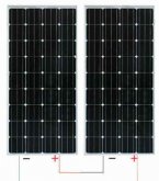
I have two panels I connected in series... Now when I test with my ohm meter for polarity the positive is negative and the negative is positive...Is this suppose to be this way? Totally confused....Thanks in advance
 
If you check the voltage on each panel separately do you see the same polarity with respect to the gender of the MC4 connector? They should be the same.

When you plug the MC4 connectors together, the same polarity will be seen across the two flyleads that aren't plugged in. Note the polarity of the MC4 connectors at the bottom of the image.

1578391827400.png
 
It makes no difference. Note the polarity indicated on the MC4 connectors at the bottom of the image. The MC4 connectors on both your panels should be the same polarity as this. Check the polarity of the voltage with your multimeter.
 
I do check with my meter and what should be the negative cable now shows as the positive... That is why I am asking..
 
Did you check each panel separately? The only way you are going to really see reversed polarity is if one of the panels has the MC4 connectors on the wrong lead.
 
Now when I test with my ohm meter for polarity the positive is negative and the negative is positive
If you put the positive probe of your multimeter set to DC Volts on the positive lead of your panel, and the negative on the negative, your multimeter should display a positive voltage. It's really is that simple.

This will measure Voc (or Volts Open Circuit) and should be around 22V for a 100W panel in full sun. Don't bother trying to measure resistance, the reading will be meaningless. If you want to measure Isc current (or Current Short Circuit) make sure your probes are connected to the 10A current ports on your multimeter and again connect the positive probe to the positive lead, negative to negative. You should get around positive 6-8A for a 100W panel in full sun. Don't leave this connected for very long e.g. few seconds only. If you want to check your panel's blocking diode, set you multimeter to diode-check, connect positive probe to positive lead, negative to negative, your meter should display the forward bias voltage of your blocking diode, probably around 0.3 or 0.4V for a schottkey diode, now switch your probes around and you should get nothing displayed i.e. your multimeter displays overload. This proves your blocking diode is functioning correctly. Checking bypass diodes and internal resistance are a bit more tricky. Google them.

I hope this helps.
Regards,
David.
 
Here is a simple diagram connecting panels in series and parallel. Regardless however you install your the panels + and - should always indicate the same polarity on your volt meter. Question - Is your voltmeter RMS
 

Attachments

  • pannel1.jpg
    pannel1.jpg
    82.4 KB · Views: 0
  • solpan1.jpg
    solpan1.jpg
    16.3 KB · Views: 0
  • pannel3.jpg
    pannel3.jpg
    123.5 KB · Views: 0
Back
Top