diy solar

diy solar

Higher amps hurt effectiveness of Built-in BMS of 12V LiFePO4s in Parallel?

sun_of_a...

New Member
Joined
Dec 17, 2023
Messages
91
Location
north carolina
RE : paralleling Litime 12V 230Ah Plus LiFePO4s

Hi and thank you.

I’m planning on making several SEPARATE 12v battery banks, and I’m trying to decide whether 4 of these batteries in parallel is my max bank size, or 6 of these is, and specifically whether the extra amps/current of 6 parallel in a 12v bank might make the built-in BMSs in each battery less effective at doing it's job balancing the battery's cells? Than is, less effective than a 4 battery 12v bank of these?

I have 16 Litime 12V 230Ah Plus Low-Temp Protection LiFePO4s. Each has a Built-In 200A BMS. No bluetooth wifi.

6 of these to a bank would be great b/c I think that’s the max recommended for a 12v Victron MultiPlus-II (based on it’s maximum charging current).

edit: I hesitate to provide a average load estimate, but let's say 2000 watts 8 hrs all night. But I would manually switch between banks for now as necessary, but that's a different question I'll have for later, i think.

Thank you forum!
 
Last edited:
Maybe increased amps/current does negatively affect how well the built-in BMSs on these paralleled 12v LiFePO4s keep cells balanced, but it only has to do with the current associated the load(s), not the amp hours or number of batteries?

As you can see, I'm a novice at this stuff. Thank you.
 
With that many batteries, you want to connect them together the BEST way possible - that is having each battery connect to a “battery bus bar” with equal cables- (length, size, etc). You are trying to get the same impedance.

That way hopefully they will share the power and loads equally. If they share the power & loads equally- you can connect a lot up in parallel. You will want a clamp on amp DDM to verify. It should not create any issues having 4 or 8 or 12 connected (provided they each have the same impedance).

Look at the Victron PowerIn w/fuses (see YouTube on how to add fuses), it make a nice easy to work with battery bus bar. You can also build your own or buy a different Copper bus bar - make sure it has plenty of amp capacity.

Remember KISS - Keep It Simple and Serviceable (I always mess up on the serviceable).
 
I don't think the extra battery capacity will make it hard for the BMS to balance although you may spend less time in the balance voltage range (above 13.6V).

In my experience once the cells are pretty well top balanced, as long as you don't run the battery down very very low they tend to stay in balance pretty well. You could use something like a NOCO genius 1A to apply a overnight charge to a full battery bank to give it some extended time to top balance once in awhile if needed.
 
With that many batteries, you want to connect them together the BEST way possible - that is having each battery connect to a “battery bus bar” with equal cables- (length, size, etc). You are trying to get the same impedance.

That way hopefully they will share the power and loads equally. If they share the power & loads equally- you can connect a lot up in parallel. You will want a clamp on amp DDM to verify. It should not create any issues having 4 or 8 or 12 connected (provided they each have the same impedance).

Look at the Victron PowerIn w/fuses (see YouTube on how to add fuses), it make a nice easy to work with battery bus bar. You can also build your own or buy a different Copper bus bar - make sure it has plenty of amp capacity.

Remember KISS - Keep It Simple and Serviceable (I always mess up on the serviceable).
Thank you Rocket very much for the reply. It sounds like my question about too much current messing up the internal BMSs of these batteries is not an issue.

I was planning on building my own bus bars from 1"x 2" copper bars 10 inches long, w/ 1ft 2/0 cables to the batteries, if i parallel 6 of them together.

I'll look at the PowerIn.

I guess the battery bank size is more relevant to the 12v Victron MultiPlus-II, I'll get, and the amp hours of the maximum recommended battery bank based on the Multiplus-II's maximum charging current?

Thank you.
 
I don't think the extra battery capacity will make it hard for the BMS to balance although you may spend less time in the balance voltage range (above 13.6V).

In my experience once the cells are pretty well top balanced, as long as you don't run the battery down very very low they tend to stay in balance pretty well. You could use something like a NOCO genius 1A to apply a overnight charge to a full battery bank to give it some extended time to top balance once in awhile if needed.
Thank you Supra,
" I don't think the extra battery capacity will make it hard for the BMS to balance although you may spend less time in the balance voltage range (above 13.6V)."

That's very interesting. I did not know about that. Maybe that suggests smaller bank size?
 
I'm in general favor of more batteries are better. I just mean that they may be at full charge less often, when the bank is generously sized. Balancing typically begins at 13.6 volts and above. Once the sun goes down and the battery is resting, Even a small load will quickly drop it below 13.6 volts and balancing will stop.
 
I’m planning on making several SEPARATE 12v battery banks,
Is there a particular reason you are sticking with 12V system? With that many batteries, i will assume you are dealing with a lot of power. 12V quickly becomes unmanageable over 2000W.

A 48V system would greatly reduce amps thereby reducing wiring and fusing requirements and constraints.

Now is the time to decide, before purchasing a lot of 12V stuff.
Thank you Sandals, yes, I did originally plan 48V system and 4s4p for these batteries, but since I really have more 12v applications right now (RV & boat) 12v is better, and I'm planning on a 48v system for my house, with individual 48v batteries so cell balancing is not so much an issue. That's my thinking. Thanks.
 
I'm in general favor of more batteries are better. I just mean that they may be at full charge less often, when the bank is generously sized. Balancing typically begins at 13.6 volts and above. Once the sun goes down and the battery is resting, Even a small load will quickly drop it below 13.6 volts and balancing will stop.
Yes, okay. But the more time above 13.6 volts the better for the health of the battery, so maybe it's a consideration on battery bank sizing and whether to use multiple 12v battery banks? I just don't know how much of a consideration is should be. I have questions I was planning for another thread about having multiple battery banks and (isolated?) 12v-12v DC chargers between them, so i guess multiple banks also relates to this question of maximizing time all batteries are above 13.6 volts. I'm in over my head here. Thanks very much.
 
Last edited:
Occasionally I run my house off 2 cheap 12V 300Ah 200A BMS LifePO4 prefabs with a 3000W Renogy LF inverter, using 6 feet of 2/0. I'll get a voltage drop measurement but I believe it's about 5% from battery terminal to inverter terminal.

The worst loads are
dryer (120V 1500W)
hot water heater (120V 1100W)
induction cooktop (1500W)
toaster oven (1500W if I recall)
microwave (1100W)
bathroom fan with heater (1300W)
jet pump Gould's 1/2hp (1100W)

So 6 of those in parallel would have no problem with a 3K. With a critical loads panel you could have 2 banks and 2 inverters for 6000W if needed.
 
Once you add up what your big wires and fuses amount to, look into what putting a 48V to 12V converter from battery to you 12V fusebox entails.

And good luck!
Thanks Sandals, I've priced big wires and bus bars, but not fuses. Battery health and balancing requirements are driving this for me i guess, but I welcome the discussion.
 
Adding more batteries in parallel means you will charge and discharge the batteries at lower C rates, which will actually help the batteries stay balanced better.

Charging at higher C rates can cause poorly matched battery cells to become more unbalanced as some cells reach high cut off faster than others, and the built in balancing can't keep up.
 
Yes, okay. But the more time above 13.6 volts the better for the health of the battery, so maybe it's a consideration on battery bank sizing and whether to use multiple 12v battery banks? I just don't know how much of a consideration is should be. I have questions I was planning for another thread about having multiple battery banks and (isolated?) 12v-12v DC chargers between them, so i guess multiple banks also relates to this question of maximizing time all batteries are above 13.6 volts. I'm in over my head here. Thanks very much.
I think the technical reason for limiting how many are in parallel relates to how a fault in one battery or BMS could overwhelm another BMS in the system, potentially leading to an unbelievably powerful short. That said I've had as many as (10) 300A prefabs in parallel before and it works just fine and the more the better.

As far as cell balancing I wouldn't worry about that either because the bigger the bank, the less it cycles. Honestly I think once they are initially top balanced you can let the BMS do the rest.

I will say though I'm a huge fan of BMS Bluetooth and couldn't live without it now. It's nice to be able to keep an eye on the cells and to have individual state of charge reading, especially if you are training for DiY mastery : )
 
Occasionally I run my house off 2 cheap 12V 300Ah 200A BMS LifePO4 prefabs with a 3000W Renogy LF inverter, using 6 feet of 2/0. I'll get a voltage drop measurement but I believe it's about 5% from battery terminal to inverter terminal.

The worst loads are
dryer (120V 1500W)
hot water heater (120V 1100W)
induction cooktop (1500W)
toaster oven (1500W if I recall)
microwave (1100W)
bathroom fan with heater (1300W)
jet pump Gould's 1/2hp (1100W)

So 6 of those in parallel would have no problem with a 3K. With a critical loads panel you could have 2 banks and 2 inverters for 6000W if needed.
Thanks for the info. Lots of electric appliances.

With a critical loads panel you could have 2 banks and 2 inverters for 6000W if needed.
Wired how, in general?
 
Adding more batteries in parallel means you will charge and discharge the batteries at lower C rates, which will actually help the batteries stay balanced better.

Charging at higher C rates can cause poorly matched battery cells to become more unbalanced as some cells reach high cut off faster than others, and the built in balancing can't keep up.
Ok, thanks QDog. Yes, that seems logical, now that you mention it.
 
As far as cell balancing I wouldn't worry about that either because the bigger the bank, the less it cycles.
Okay, that's what QDog says too. Bigger is better for health of batteries.
Honestly I think once they are initially top balanced you can let the BMS do the rest.
You mean the individual 200amp built-in BMSs on each of these 230ah batteries?

Re bluetooth, yep, I think I thought they were. Maybe that's all the more reason to just go 12v battery banks w/ these batteries, instead of 24 or 48 volt wired in series. In parallel there's much less need to disconnect and test them individually, right?

Thank you.
 
If we were theoretically talking about a full size home, wiring to code would require a full size transfer switch, appointment with the power company and electrician while switch is being installed, inspections permits etc. Suddenly the project goes from a simple $300 inverter backfeed to a possibly $1XXXX fiasco, might as well go 48V fancy inverter for that money.

BUT in an emergency like extended grid down or if you are way off grid, you could feed one 3,000W inverter to the main panel circuits and the other 3,000W would back feed into a critical loads / transfer switch box. You could use a split phase 240V inverter OR jump the legs together to make the entire house 120 volts, being mindful not to overload (or get rid of) any shared neutrals.

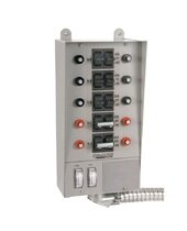
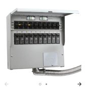
The critical loads / transfer switch panels can easily be installed to code. They have an input for 120V or 240V backfeed cable and three-way switches with breakers built in, for 6, 10 or 12 circuits. The wires from that panel reach into the main panel. One wire taps into the breaker for each circuit you choose and the other wire taps into the load side of that circuit. That way you can switch loads back and forth from one inverter to the other, or the grid, as needed or if needed. It also allows you some flexibility, you could backfeed the critical loads panel with a generator or an inverter from an entirely different battery system like a 24 or 48 volt or a portable power station.

Wiring the panel is a lot easier than it sounds written in a paragraph, no problem if you have wiring skill or can be quickly wired by and electrician. The.transfer switches are expensive but I often see them cheap on Facebook marketplace.
 

Attachments

  • Screenshot_20240108_163738_eBay.jpg
    Screenshot_20240108_163738_eBay.jpg
    122.5 KB · Views: 1
  • Screenshot_20240108_165116_Chrome.jpg
    Screenshot_20240108_165116_Chrome.jpg
    79.9 KB · Views: 1
If we were theoretically talking about a full size home, wiring to code would require a full size transfer switch, appointment with the power company and electrician while switch is being installed, inspections permits etc. Suddenly the project goes from a simple $300 inverter backfeed to a possibly $1XXXX fiasco, might as well go 48V fancy inverter for that money.

BUT in an emergency like extended grid down or if you are way off grid, you could feed one 3,000W inverter to the main panel circuits and the other 3,000W would back feed into a critical loads / transfer switch box. You could use a split phase 240V inverter OR jump the legs together to make the entire house 120 volts, being mindful not to overload (or get rid of) any shared neutrals.

The critical loads / transfer switch panels can easily be installed to code. They have an input for 120V or 240V backfeed cable and three-way switches with breakers built in, for 6, 10 or 12 circuits. The wires from that panel reach into the main panel. One wire taps into the breaker for each circuit you choose and the other wire taps into the load side of that circuit. That way you can switch loads back and forth from one inverter to the other, or the grid, as needed or if needed. It also allows you some flexibility, you could backfeed the critical loads panel with a generator or an inverter from an entirely different battery system like a 24 or 48 volt or a portable power station.

Wiring the panel is a lot easier than it sounds written in a paragraph, no problem if you have wiring skill or can be quickly wired by and electrician. The.transfer switches are expensive but I often see them cheap on Facebook marketplace.
Great! Thanks so much Supra for taking the time and breaking it down like that. I will begin to think in terms of a separate critical loads panel for home, and RV also as 12v backup for home. The two MultiPlus-IIs would not be paralleled in you above scenario, right? Thanks.
 
Back
Top