diy solar

diy solar

How critical are identical lengths on parallel wired batteries?

I've been digging through the forum and I'm seeing multiple posts about how batteries wired in parallel should have identical length wires between them.
There are so many opinions and minutia.
Please have a look at this PDF from Victron Systems who "know" what they are doing and do explain things nicely.
Specificaly refer to Page 18 "3.3 Parallel battery bank wiring" and forward.

This is one of a few subjects which can easily invoke the proverbial "Beating of the dead horse".
Beating_Dead_Horse.gif
 
There are so many opinions and minutia.
Please have a look at this PDF from Victron Systems who "know" what they are doing and do explain things nicely.
Specificaly refer to Page 18 "3.3 Parallel battery bank wiring" and forward.
But that doesn't really answer the OP's original question. There are not enough specifics in regard to the "diagonal" wiring method in Victron's document.

The only relevant statement I see in Victron's document is:
The correct way of connecting multiple batteries in parallel is to ensure that the total path of the current in and out of each battery is equal.

But there are no details about how that specifically applies to the diagonal method. That is the point of post #6 in this thread. I believe the constraints I've outlined in that post satisfy the above statement from Victron but I'm hoping someone can verify. If I'm correct then the OP has a balanced parallel battery bank despite the longer "center" wires.
 
Sortof. But not really because:

A 12V lead acid battery is never actually full unless equalizing at 15.6V or so. Believe it or not. So absorption isn’t bumping against a ceiling if 14.4 exists. Or 13.8. The lead acid battery needs 10-15% above cell voltage to actually be charging so to a large extent the battery with the higher voltage just sits there and takes it, still reduced current capacity exists at “the next” battery, and everything starts to ‘balance’ but it could take a week to balance if you weren’t using anything.

The math and empirical science says that will happen but in practice? In the real world? Not really. But eventually yes, but after what stress to the battery that hangs at lower voltages?

Balance the cables, bulk in the mid 14s, and float 13.8 is the best outcome. Batteries aren’t a machine: we just inflict daily damage in the least destructive manner possible to create a useful lifespan we can live with. That’s not science, but it’s how I’ve gotten surprisingly long life out of cheap batteries for… 25? years?
I was thinking LFP, not FLA. given how quickly the IR changes above the knee is what got me to thinking about this.
 
If I had it to do over I'd change the layout (and the voltage), but now that it's assembled, the cable has been paid for, etc. I'm hoping this turns out to be more like instead of 7000 cycles, you'll get 6950 cycles or something like that. I'm sure we've all seen that technical folks like ourselves, especially enthusiasts, pick everything apart for every conceivable improvement and they are real, measurable, and understandable. They are also often so minor that nobody but the enthusiast will notice or care. 30 extra horsepower in a 600 hp engine, .25 MOA on a rifle at 500 yards, etc. Thus it becomes hard to tell what is a real world problem for "regular" people when digging through a forum for enthusiasts. :)

For me, this isn't a high load, cycle every day system as of yet. With 2/3 of the country predicted to have rolling blackouts this summer and gas over $5 I've just been slowly putting together something that I can use intermittently when required and become more familiar with the systems. If I get too worried I suppose I could rotate the batteries occasionally as well.

Also, thanks for the responses. Having this discussion is sparking ideas and has already pointed me to literature I hadn't seen before.
 
The Victron lynx system is pretty much the state of the art IMO.
Its from the folks you brought you Wiring Unlimited.

A typical topology would be...

lynx_power_in<->lynx_shunt<->lynx_distributor

The lynx_power_in is an un-fused busbar to which up to 4 batteries can be paralleled.
The lynx_shunt is self explanatory
lynx_distributor is a fused busbar to which the loads and sources are paralleled.

The busbars are 240mm2 so the incremental resistance along the busbar in most use cases is just noise compared to the resistance of the joinery to and between the lynx components.

I would still make sure the total path resistance of each battery circuit was as close as practically possible.
 
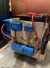
No your diagram is not balanced. I am forced to agree with 12voltinstalls. His diagram is like number 4 in this aragements. http://www.smartgauge.co.uk/batt_con.html
Numbering OP battery as right to left top down. (1) (2) (3) (4). Connect (2+) onto (4+). Connect positive switch to (2+). Connect (1-) onto (3-). Connect system negative onto (3-). The shorter interconnections can stay as they are. Each shorter positive cable must be the same length. Each shorter negative cable must be the same length. Negative not need be same as positive. But it help. .Now we need to talk about fuses.
Ah yup I think I like this. It's get me to Method 4 which is described as optimum and all I'd need to purchase is one longer negative cable. This is turning a mistake into a feature. Brilliant! Thank you!
 
  • Like
Reactions: Zil
I was thinking LFP, not FLA. given how quickly the IR changes above the knee is what got me to thinking about this.
LFP have BMS. LiFePo should begin balanced in their assemblies, and the bms should maintain that. I’m not a LiFePo guy but maybe bone of the usual suspects can confirm that uneven length cables do not matter bro LiFePo battery banks. Or not.
I have no trivial information about that.
 
The Victron lynx system is pretty much the state of the art IMO.
Its from the folks you brought you Wiring Unlimited.

A typical topology would be...

lynx_power_in<->lynx_shunt<->lynx_distributor

The lynx_power_in is an un-fused busbar to which up to 4 batteries can be paralleled.
The lynx_shunt is self explanatory
lynx_distributor is a fused busbar to which the loads and sources are paralleled.

The busbars are 240mm2 so the incremental resistance along the busbar in most use cases is just noise compared to the resistance of the joinery to and between the lynx components.

I would still make sure the total path resistance of each battery circuit was as close as practically possible.
Trust me, I'm a pretty big fan. ;)
battery2.jpg
 
LFP have BMS. LiFePo should begin balanced in their assemblies, and the bms should maintain that. I’m not a LiFePo guy but maybe bone of the usual suspects can confirm that uneven length cables do not matter bro LiFePo battery banks. Or not.
I have no trivial information about that.
Some of the stuff I've been reading has stated that since the LiFePO batteries have a smaller internal resistance they are more susceptible to imbalance, but many including mine do have the onboard BMS. Though they are internal and don't communicate so I'm not sure if they are relevant for this. More reading I guess. :)
 
Isn't it true that with over-sized cables and charging current not excessive the difference in voltage to the batteries is so small as to not really be a problem in the case of the OP's system?
 
I've often wondered about this question myself. So I'll ask it here instead of starting yet another thread...

With regards to FLA batteries...
Using the Bus-Bar method...
2s4p batteries (8 total)...

How exact do the wire lengths need to be? Is being 1" short going to affect the balance a noticeable amount? How about 6"? 12"? Do the Pos and Neg wires all have to be the same length as each other?
 
Back
Top