Great.That looks pretty good to me.
Are you planning on having loads that need more than the 6.8KW of the inverter when it is in passthrough? The reason I ask is that when I design for a main box separate from the critical load box, I don't typically load up the critical load box with more than what the inverter can drive..
If your loads are never going to exceed what the inverter can drive, then the max continuous current is 6800W/240=28.3A. With that current you could use a breaker sized at 28.3 x 1.25 = 35.41A. Round up to 40A for the breakers and 8AWG for the wires.
So the plan was to run my AC unit and charge the batteries and few loads at peak. So I charge my batteries at night (after 8pm) and the AC would be running at the same time with few other loads
AC would be around 12-13A(run) and surge to around 32A(with a softstart). I would be charging the batteries at around 2 KW. So without any additional loads, it would total around 5000w. With some additional load, it would probably come close to 5500-6000w (guessing). Schneider recommended 60A but I think they would max rate at 80% of that (48A -- info from XW doc and other boards). I already have it wired with 6 AWG & 60A and it seems to be working without issues (tried out the AC and it worked). Just wanted to make sure about the ground connections one more time.
So the DC ground is not needed, right?
thank you
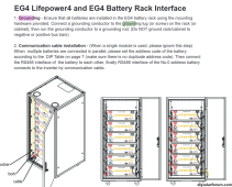
Ground points - Would that be from negative bus bar to the rack since they are all in parallel?Lets start with the easy part of the answer. You should definitely ground the rack and tie the ground points of the batteries to the Rack. Typically people will daisy chain all the battery ground points together and then one connection to the rack.
The more difficult part of the answer is whether the DC circuit itself should be grounded. Most people don't ground the circuit. However, this does not square with the part of the NEC code that says any circuit over 50V should be grounded (Either the negative side or positive side, the code does not specify). This quandary has always left me a bit uneasy..... particularly since I don't know what the equipment is expecting. Will the inverter or battery get upset with a grounded circuit? Does the inverter keep the DC circuit from floating significantly above earth ground? I used to recommend grounding the DC circuit because, in general, floating circuits are not a good thing ..... but now I am not as convinced. As I said, it seems like most people don't ground the DC circuit and the inspectors don't flag it.


