I tested the grounding of the AIMS 12v to 220v split phase inverter with a plug in receptacle tester. It shows that while in battery mode that the neutral is internally bonded to ground, therefore the neutral and ground are not bonded at the panel.


You are using an out of date browser. It may not display this or other websites correctly.
You should upgrade or use an alternative browser.
You should upgrade or use an alternative browser.
How does your inverter deal with ground.
- Thread starter FilterGuy
- Start date
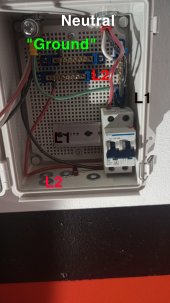
I have a PowerJack rebranded chinese inverter. Neutral floats, and is not bonded to ground. Chassis ground is not connected to neutral nor should it be. The device uses a single center tapped non isolating transformer. Chassis ground is not a return path for AC for that device. I bonded neutral and created a fake ground in a wiring box, it will act as a return path and outlets test ok.
Chassis ground can be attached to a metal body and a ground stake can be attached, but it should not be connected to any part of mains, and grounding the trailer frame with bat neg would result in a hot skin scenario with this inverter as voltage can flow from AC to DC due to no isolation transformer.
I have seen mounting bolts glow red where people have bonded neutral and ground on these.
Eventually will upgrade to a system that supports neutral ground bond in the inverter itself.
I do feel these inverters carry a bit of danger. A misplaced screw touching a trailer shell and you have a hot skin.
Attachments
Last edited:
You just explained very well what happened at a place I worked at years ago…it was part retail in front of a diesel repair shop in the back with the most God awful electric system thst was 60 + years old and had been modified by the old timers working there a hundred times ..they had ground rods everywhere you looked , wore out wires run here and there…it was scarey to look at..Definitely not a good idea, on a rainy day.
I should add a disclaimer. lol
I could lean on the metal sales counter touching my forearm and feel a uncomfortable shock while wearing rubber sneakers and standing on 3 layers of carpet ..it worried me so I wouldn’t step on the bare concrete floor while touching the counters..half the equipment in there nipped you when ya touched it…
they said , it’s alway done that..No Biggie.
when it rained literally tens of thousand of worms (, many 5 gallon bucket fulls) , sufaced from the ground everywhere and died for no reason soon afterwards….and covered the parking lot, crawled in the store and garage doors, covered the diesil shop area so thick they used a floor squeegee and water hose to push em back out side…
I had to take a regular broom and swish a path to my truck after work to avoid having mucky feet from walking on worms.. when the sun came out all the rotting worms stunk to high heaven..
I was new there…it was about an acre of land and parking..it was creepy..
I ask them the first month , what the Hell l is going on here.? This is like being in a Stephen King movie…
The old guys replied , Awwww it’s always been that way…you get used to it…
I said haaaaaaaaaa I QUIT…
I never understood the whole electrified sales counter or “worm thing” untill getting into solar and learning about grounding and worms from the forum guys.
J.
Last edited:
timselectric
If I can do it, you can do it.
- Joined
- Feb 5, 2022
- Messages
- 18,836
That's a N/G bond. Nothing fake about it.I bonded neutral and created a fake ground in a wiring box
That's the beginning of a standard grounding system.
What's fake is I can't bond it to the inverter ground, the bat neg terminal, the shell of the trailer etc. It's a local only ground, an alternate path to get back to the center tap of the transformer.That's a N/G bond. Nothing fake about it.
That's the beginning of a standard grounding system.
It's not possible to do fully properly without an isolation transformer somewhere in the chain I think, and usually good inverters have those built in. At some point I am gonna eye the Aims , Genetry Solar, or Renogy inverter. I want a low freq one as I am running power tools off it.
The way they built that inverter, no current can flow directly through a low impedance path from any of the transformer taps to the ground screw or bat neg. There is a voltage potential between any transformer tap and bat neg, and if there was no load, current would flow and make smoke and fire.
Ideally, I feel, everything could be bonded, and then a stake driven into the earth providing both electrostatic and shock protection.
I wonder if it is worth adding an isolation transformer on the output as is...
Last edited:
timselectric
If I can do it, you can do it.
- Joined
- Feb 5, 2022
- Messages
- 18,836
The only thing that needs to be isolated is the battery negative (and positive of course).What's fake is I can't bond it to the inverter ground, the bat neg terminal, the shell of the trailer etc. It's a local only ground, an alternate path to get back to the center tap of the transformer.
But if the battery is part of the starting system. You can't isolate it.
The battery is isolated, not a starter battery. It's isolated by virtue of having two dedicated #0000 wires run for bat neg and pos to a breaker and a bus bar, and to the inverter. No trailer shell connection.
The best I got for "grounding" on this is an AC circuit specific AC ground and neutral tie, and probably staking the trailer shell and attaching the inverter ground to the shell. The shell can't be connected to neutral or bat neg. It'd be an electrostatic ground only.
The inverter documentation specifically calls out not binding neutral to bat neg or inverter ground, it has to float ?
I just don't like it, it's possible to get a shock by grabbing either bat terminal and AC neutral. Not that I would do that intentionally.
An inverter that ties neutral to ground internally, and has an isolation transformer would be safer. I have to be mindful of screw depth and stuff and metal to metal contact in lieu of a good inverter.
timselectric
If I can do it, you can do it.
- Joined
- Feb 5, 2022
- Messages
- 18,836
So, battery negative is internally connected to the inverter enclosure.The battery is isolated, not a starter battery. It's isolated by virtue of having two dedicated #0000 wires run for bat neg and pos to a breaker and a bus bar, and to the inverter. No trailer shell connection.
The best I got for "grounding" on this is an AC circuit specific AC ground and neutral tie, and probably staking the trailer shell and attaching the inverter ground to the shell. The shell can't be connected to neutral or bat neg. It'd be an electrostatic ground only.
The inverter documentation specifically calls out not binding neutral to bat neg or inverter ground, it has to float ?
I just don't like it, it's possible to get a shock by grabbing either bat terminal and AC neutral. Not that I would do that intentionally.
An inverter that ties neutral to ground internally, and has an isolation transformer would be safer. I have to be mindful of screw depth and stuff and metal to metal contact in lieu of a good inverter.
In that situation you will have to leave the AC output floating. I would at least use a GFCI.
And replace it with something safer, as soon as possible.
Hedges
I See Electromagnetic Fields!
- Joined
- Mar 28, 2020
- Messages
- 20,861
What's fake is I can't bond it to the inverter ground, the bat neg terminal, the shell of the trailer etc. It's a local only ground, an alternate path to get back to the center tap of the transformer.
I bonded neutral and created a fake ground in a wiring box, it will act as a return path and outlets test ok.
I do feel these inverters carry a bit of danger. A misplaced screw touching a trailer shell and you have a hot skin.
Do you mean you bonded neutral to the ground pin of an outlet? If so, and if neutral can't be bonded to chassis because current will flow, it sounds like chassis of any device (e.g. corded drill) with 3-prong plug would be hot, a shock hazard.
I wonder if it is worth adding an isolation transformer on the output as is...
I'd like to. But typical transformers partially saturate, would be a bad load on the inverter. Some transformers, and wiring a transformer differently (apply 120V to a 240V primary winding) could be better.
In that situation you will have to leave the AC output floating. I would at least use a GFCI.
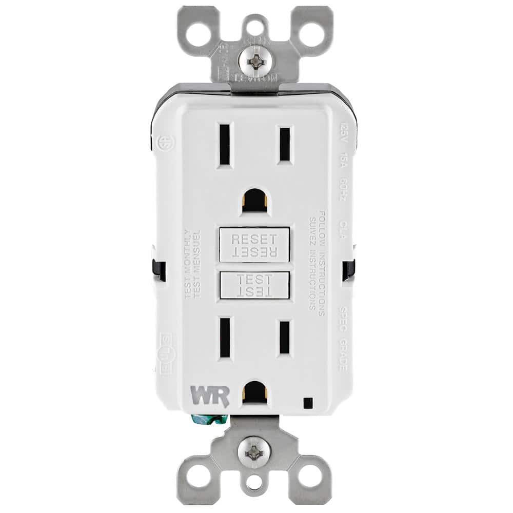
I would use GFCI with L and N connected, ground left unconnected. Leviton works, the Eaton I tried did not.
timselectric
If I can do it, you can do it.
- Joined
- Feb 5, 2022
- Messages
- 18,836
RightI would use GFCI with L and N connected, ground left unconnected. Leviton works, the Eaton I tried did not.
I remember that.
No more Eaton in my inventory.
Hedges
I See Electromagnetic Fields!
- Joined
- Mar 28, 2020
- Messages
- 20,861
Nothing wrong with Eaton. I would think better quality. It's just that they put in a feature to prevent operation with L/N swapped, and that only works if ground is present. Just not good for old houses with ungrounded outlets.
I ordered cartons of both, for different properties.
I do want to figure out why even circuits with BX don't seem to show continuity to BX, but when I test to a water pipe they do. It looks connected at both ends.
I ordered cartons of both, for different properties.
I do want to figure out why even circuits with BX don't seem to show continuity to BX, but when I test to a water pipe they do. It looks connected at both ends.
timselectric
If I can do it, you can do it.
- Joined
- Feb 5, 2022
- Messages
- 18,836
Eaton won't work in some situations.Nothing wrong with Eaton.
I won't be stocking two different brands for two different situations. When Leviton works everywhere.
Do you mean you bonded neutral to the ground pin of an outlet? If so, and if neutral can't be bonded to chassis because current will flow, it sounds like chassis of any device (e.g. corded drill) with 3-prong plug would be hot, a shock hazard.
Well, current would not flow to chassis if I connected neutral to chasis. Right now chassis is floating. Current would flow of I connected bat neg and neutral to chassis. Current may flow if I connect inv chassis to chassis, and neutral to chassis. Inv chassis does not seem to be bonded to bat neg terminal internally according to multimeter. There is some sort of decoupling cap specifically on inv ground pin.
I would rather not connect neutral to chassis, as if for some reason there is a short, chassis would be the return path. While everything is on a breaker, theres enough current probably to blow holes in it. Since neutral floats on the output transformer and doesn't necessarily sit at 0v, bonding that to the trailer skin seems worse than letting the trailer skin float disconnected with some stray capacitance.
There is a few volts of stray voltage between neutral and chassis in the form of some sort of capacitance, but it quickly falls to nothing when I touch the multimeter to it.
I think the best thing to do is to invest in a good inverter in my case, and let the chassis float or be tied to earth.
This is just my opinion, not an electrical engineer, but I am following the manual for the inverter.
Electrically there is no continuity between chassis and anything right now. My intent is to follow the manual and connect inv ground to chassis and chassis to earth. According to the manual, I cannot bond bat neg and neutral, inv ground and neutral, and bat neg to chassis and inv ground seems like a recipe for bad disaster as current would flow from inv neutral to chassis in that config. The inverter has placed a lot of restrictions on grounding. ?
Last edited:
Hedges
I See Electromagnetic Fields!
- Joined
- Mar 28, 2020
- Messages
- 20,861
So all "WR"?
I've thought Leviton might be inferior quality, but not certain. Seems to be Home Depo's usual brand, and they've cheaped out on some things. Same with Feit light bulbs, they stopped carrying name brands and started stocking those.
I have had a few GFCI outlets stop working. GFCI breakers seem to be more durable (except when I put a short on one.)
Maybe my problem with outlets was I didn't know about WR. Some mention conformal coat on boards.
Leviton 15 Amp 125-Volt Duplex Self-Test Tamper Resistant/Weather Resistant GFCI Outlet, White R92-GFWT1-0KW - The Home Depot
Peace of mind, all the time. The SmartlockPro Self-Test GFCI tests itself even if you forget. Designed to meet the latest UL standard for auto-monitoring (self-test), our complete line of self-test GFCIs
www.homedepot.com
I've thought Leviton might be inferior quality, but not certain. Seems to be Home Depo's usual brand, and they've cheaped out on some things. Same with Feit light bulbs, they stopped carrying name brands and started stocking those.
I have had a few GFCI outlets stop working. GFCI breakers seem to be more durable (except when I put a short on one.)
Maybe my problem with outlets was I didn't know about WR. Some mention conformal coat on boards.
Hedges
I See Electromagnetic Fields!
- Joined
- Mar 28, 2020
- Messages
- 20,861
Well, current would not flow to chassis if I connected neutral to chasis. Right now chassis is floating. Current would flow of I connected bat neg and neutral to chassis. Current may flow if I connect inv chassis to chassis, and neutral to chassis. Inv chassis does not seem to be bonded to bat neg terminal internally according to multimeter. There is some sort of decoupling cap specifically on inv ground pin.
I figured battery might get driven to AC voltage with these sorts of inverters if neutral bonded to ground. It would really surprise someone if +12VDC is riding on top of 60Vrms AC. Car battery of course would have negative bonded to chassis.
I prefer stuff that works the way house wiring is supposed to.
I think the best thing to do is to invest in a good inverter in my case, and let the chassis float or be tied to earth.
Yes, good properly connected inverter. Maybe use cheap one for portable/backup. Hard to deal with ground in a mobile application, but GFCI is always good unless it cuts power to your refrigerator.
hi @FilterGuy - Could you please review these connections? I
had asked in other groups but wanted to double/triple confirm. I have a Schneider XW pro 6.8k inverter with mini-pdp with connections to main, batteries and sub-panel. I have AC ground coming in from the main but no ground going to the sub-panel from the inverter. I have Ground connected between main and sub-panel(6 awg). The XW document says to connect from XW to sub-panel but in the diagrams that they have, it does not have a connection from the XW to sub-panel.
Also, do I need to ground the DC side?

DOC:

Diagram from Doc:

Another sheet from their documentation:

thank you
had asked in other groups but wanted to double/triple confirm. I have a Schneider XW pro 6.8k inverter with mini-pdp with connections to main, batteries and sub-panel. I have AC ground coming in from the main but no ground going to the sub-panel from the inverter. I have Ground connected between main and sub-panel(6 awg). The XW document says to connect from XW to sub-panel but in the diagrams that they have, it does not have a connection from the XW to sub-panel.
Also, do I need to ground the DC side?
DOC:
Diagram from Doc:
Another sheet from their documentation:
thank you
FilterGuy
Solar Engineering Consultant - EG4 and Consumers
That looks pretty good to me.hi @FilterGuy - Could you please review these connections? I
had asked in other groups but wanted to double/triple confirm. I have a Schneider XW pro 6.8k inverter with mini-pdp with connections to main, batteries and sub-panel. I have AC ground coming in from the main but no ground going to the sub-panel from the inverter. I have Ground connected between main and sub-panel(6 awg). The XW document says to connect from XW to sub-panel but in the diagrams that they have, it does not have a connection from the XW to sub-panel.
Also, do I need to ground the DC side?
View attachment 179833
DOC:
View attachment 179834
Diagram from Doc:
View attachment 179835
Another sheet from their documentation:
View attachment 179836
thank you
Are you planning on having loads that need more than the 6.8KW of the inverter when it is in passthrough? The reason I ask is that when I design for a main box separate from the critical load box, I don't typically load up the critical load box with more than what the inverter can drive..
If your loads are never going to exceed what the inverter can drive, then the max continuous current is 6800W/240=28.3A. With that current you could use a breaker sized at 28.3 x 1.25 = 35.41A. Round up to 40A for the breakers and 8AWG for the wires.
FilterGuy
Solar Engineering Consultant - EG4 and Consumers
BTW: you could have a ground from the sub-panel or the ground from the main panel to the sub-panel, but don't do both (It would create a ground loop)hi @FilterGuy - Could you please review these connections? I
had asked in other groups but wanted to double/triple confirm. I have a Schneider XW pro 6.8k inverter with mini-pdp with connections to main, batteries and sub-panel. I have AC ground coming in from the main but no ground going to the sub-panel from the inverter. I have Ground connected between main and sub-panel(6 awg). The XW document says to connect from XW to sub-panel but in the diagrams that they have, it does not have a connection from the XW to sub-panel.
Also, do I need to ground the DC side?
View attachment 179833
DOC:
View attachment 179834
Diagram from Doc:
View attachment 179835
Another sheet from their documentation:
View attachment 179836
thank you
Ampster
Renewable Energy Hobbyist
I use the main ground which is connected to my main panel and my inverter and subpanels all have ground wires going to that common ground which is routed inside one of my wiring troughs.
FilterGuy
Solar Engineering Consultant - EG4 and Consumers
Lets start with the easy part of the answer. You should definitely ground the rack and tie the ground points of the batteries to the Rack. Typically people will daisy chain all the battery ground points together and then one connection to the rack.Also, do I need to ground the DC side?
The more difficult part of the answer is whether the DC circuit itself should be grounded. Most people don't ground the circuit. However, this does not square with the part of the NEC code that says any circuit over 50V should be grounded (Either the negative side or positive side, the code does not specify). This quandary has always left me a bit uneasy..... particularly since I don't know what the equipment is expecting. Will the inverter or battery get upset with a grounded circuit? Does the inverter keep the DC circuit from floating significantly above earth ground? I used to recommend grounding the DC circuit because, in general, floating circuits are not a good thing ..... but now I am not as convinced. As I said, it seems like most people don't ground the DC circuit and the inspectors don't flag it.
Similar threads
- Replies
- 76
- Views
- 2K
- Replies
- 1
- Views
- 133
- Replies
- 3
- Views
- 174
- Replies
- 1
- Views
- 181