diy solar

diy solar

How fast will multiple LifePo4 batteries in parallel charge from 30amp shore power?

crayfish21

New Member
Joined
Mar 12, 2022
Messages
8
I'm confused how 30a at 120v from shore power gets translated through an inverter/charger into a 12v battery bank.

For example, if I have six 206ah SOK 12v batteries wired in parallel and I'm charging from 30a shore power via a Victron Multiplus inverter/charger, how much will each battery be charged per hour (assuming I'm only using shore power to charge batteries)?

Will my 1236ah battery bank be fully charged from empty in:

7 hours (charging at a rate of 30a per battery per hour?
40 hours (charging at a rate of 5a per battery per hour?
Or neither, because the charging amperage is different than the shore power amperage because of the change from 120v to 12v?

If I'm understanding the Victron Multiplus inverter/charger data sheet correctly, the 3000w models can charge batteries at a current up to 120a while the 2000w is up to 80a. With a 30a 120v shore power connection, is there no theoretical difference in battery charge speed performance between the two models? Or is the 30a from shore power at a higher amperage once it gets converted to 12v by the Multiplus?

According to the SOK data sheet, recommended charge current is 40a. Is my understanding correct, that if I were to send 120a from the Victron to the six batteries, it would be divided amongst the batteries at roughly 20a per battery?

Thanks for the help!
 
30A is 120VAC input current limit. This is approximately 3600W

3600W/12V * .85 = 255A total potential output @ 12V from 30A 120VAC input (.85 is efficiency).

1236Ah / 80A = 15.5h
1236Ah / 120A = 10.3h

This assumes you have a fantastic installation, proper configuration, etc. Thin wires, bad connections and poor ventilation means you always get less than the 80 or 120A spec.

Both units use less then the 255A 12V potential supplied by a 30A/120VAC input, so the 30A shore power isn't the limiting factor. It's the charger output that limits charging speed.

Sending 120A to six batteries will only evenly divide them to 20A each in a perfect world. The distribution depends on the quality of your install. It will never be perfect, but it can be close enough. You could easily end up with 100A going into 1 battery and 20A being split unevenly into the other 5 batteries.

Consult Victron Wiring Unlimited.
 
If I'm understanding the Victron Multiplus inverter/charger data sheet correctly, the 3000w models can charge batteries at a current up to 120a while the 2000w is up to 80a.
This is what defines the charge current.

You have 6 206Ah batteries for a total of 1236Ah. 1236Ah / 120A = 10.3 hours. 1236Ah / 80A = 15.45 hours.

With 6 batteries in parallel, each with a 40A recommended charge current, you can charge them up to 240A. Since the MultiPlus will only do 80A or 120A depending on the model, you could also charge via solar at the same time with no issue.
 
I'm confused how 30a at 120v from shore power gets translated through an inverter/charger into a 12v battery bank.

For example, if I have six 206ah SOK 12v batteries wired in parallel and I'm charging from 30a shore power via a Victron Multiplus inverter/charger, how much will each battery be charged per hour (assuming I'm only using shore power to charge batteries)?

Will my 1236ah battery bank be fully charged from empty in:

7 hours (charging at a rate of 30a per battery per hour?
40 hours (charging at a rate of 5a per battery per hour?
Or neither, because the charging amperage is different than the shore power amperage because of the change from 120v to 12v?

If I'm understanding the Victron Multiplus inverter/charger data sheet correctly, the 3000w models can charge batteries at a current up to 120a while the 2000w is up to 80a. With a 30a 120v shore power connection, is there no theoretical difference in battery charge speed performance between the two models? Or is the 30a from shore power at a higher amperage once it gets converted to 12v by the Multiplus?

According to the SOK data sheet, recommended charge current is 40a. Is my understanding correct, that if I were to send 120a from the Victron to the six batteries, it would be divided amongst the batteries at roughly 20a per battery?

Thanks for the help!

In addition to what those guys said, you can also get yourself an amp clamp (inductive) amp meter so you can take some realtime measurements on the charging amps (if you don't have a permanent shunt installed to meter/monitor), and do some math with it...

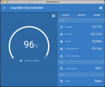
If you are into Victron stuff, I really like the BMV-712 shunt/monitor to measure SoC and see all stats on charging/discharging, Time Remaining, etc... It takes the math out of it and gets you quick numbers at a glance...

1657391966422.png
 
Last edited:
Thanks so much @sunshine_eggo @rmaddy and @Samsonite801 !!!

So if I understand correctly, if instead of shore power I have a gas generator that outputs 2000w at 120v it would be:
2000W/12V * .85 efficiency = 141A

So the generator would charge the batteries at the same speed as the shore power:

Victron 2000w - 1236Ah / 80A = 15.5h
Victron 3000w - 1236Ah / 120A = 10.3h

One other question... if I'm wiring 12v batteries in parallel does the inverter/charger care about the total size of the battery bank? In other words, do I need to wire differently for a 12v 3-battery system that combines to 618ah than a 12v 6-battery system that combines to 1236ah?

Thanks!
 
The Victron's your linking to charge either 80 or 120A, depending on the model.

With 6 batteries, each battery will be charged with 1/6th of this current, so 13 or 20A

It doesn't matter what your hookup is, as long as it can provide sufficient power. 120A @ 12V is 1440W, add some losses so you're looking into 1500W from the grid, which is around 13A at 120V.

If the shore power can provide 30A, no problem, it's only not using that for charging. But keep in mind additional loads are also powered by the grid, so if you run a 1000W electric water heater AND charge at full 120A, the incoming total is 2500W, thus approx 21A

Charging a completely empty bank (1236Ah) takes 16 or 11 hours (not exactly, current slightly drops and you're using some power while charging as well, but it's an estimate)

The charger doesnt care about the amount of batteries. It just provides (max) the current it can and that's all. If you have a BMV, you need to setup the actual capacity in order for it to give an accurate reading.

And you have to wire properly, especially with big banks (short current can be massive - use proper fuses, cables and lugs!)
 
Except it is not 12 volts.... closer to 14.0 to 14.5 while charging at the top.
And with a generator there is an issue of power factor where 5% to 30% could be unusable.
Also a "2000" generator is often rated at 1600 continuous watts.
Even 100 amps would be pushing a 2000 watt generator pretty hard. Charge current can be limited by the Victron if needed to prevent overload.
 
Is your charger 30A at 12v? That's only ... 360 watts.. It will take forever. That's why I have 48v. 30A at 48v is 1400w! vs 360w.

Confusingly you say you have 30A at 120v available. What NEMA plug is that? Do they even make a 30A plug? I seem to remember there's some special NEMA plug (quick search found "NEMA L5-30R Locking Receptacle 120V, 30A")... are you seriously using that? You'd be better off at 240v.

But again, ... I am confused. If you have 30A at 120v available, and somehow plugged it in.... That's 3600 watts charging capacity. But does your charger convert 120v to 12v? That would be a _300A_ 12v charger. I don't believe they make anywhere near that size. In 48v that'd be only a 75A charger, which is pretty big but not impossible.
 
With six batteries it will be very easy to get charge imbalances. The best method is to connect each battery to a buss bar with equal length cables.
 
Last edited:
Thanks so much @sunshine_eggo @rmaddy and @Samsonite801 !!!

So if I understand correctly, if instead of shore power I have a gas generator that outputs 2000w at 120v it would be:
2000W/12V * .85 efficiency = 141A

Yes, but you should also consider the points @time2roll made.

So the generator would charge the batteries at the same speed as the shore power:

Victron 2000w - 1236Ah / 80A = 15.5h
Victron 3000w - 1236Ah / 120A = 10.3h

Yes, but you may need to throttle it back. It would have been more accurate for me to say:

2000W/14.5V * .85 = 117A, so the 2000W generator likely can't run the full 120A.

One other question... if I'm wiring 12v batteries in parallel does the inverter/charger care about the total size of the battery bank? In other words, do I need to wire differently for a 12v 3-battery system that combines to 618ah than a 12v 6-battery system that combines to 1236ah?

That's part of the point I was trying to make about how you build the bank. The number of batteries can improve/lesson your chances of balance. Consult Victron Wiring Unlimited.
 
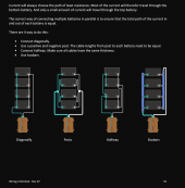
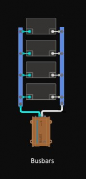
I'm looking at the image posted by @Samsonite801 (post #11) and notice the 'Diagonally' and 'Busbars' setups have a very short cable (green) to one side of the battery bank and a much longer cable (white) to the other side. That can't be good, can it?
 
I'm looking at the image posted by @Samsonite801 (post #11) and notice the 'Diagonally' and 'Busbars' setups have a very short cable (green) to one side of the battery bank and a much longer cable (white) to the other side. That can't be good, can it?
Those two different lengths between the battery bank and the loads is completely irrelevant (though you don't want them excessively long to avoid voltage drop of course).

What matters is that each battery in parallel has the same resistance between the common points in the wiring layout.
 
I'm looking at the image posted by @Samsonite801 (post #11) and notice the 'Diagonally' and 'Busbars' setups have a very short cable (green) to one side of the battery bank and a much longer cable (white) to the other side. That can't be good, can it?

@rmaddy covered it.

FWIW, if you ever find yourself in disagreement with a Victron source, you're almost certainly wrong.
 
I'm looking at the image posted by @Samsonite801 (post #11) and notice the 'Diagonally' and 'Busbars' setups have a very short cable (green) to one side of the battery bank and a much longer cable (white) to the other side. That can't be good, can it?
In these wiring diagrams, the sum of "-" and "+" cable lengths to each battery pack is equal (among the 4 battery packs being wired in parallel). To and from each specific battery, a difference between the cable resistance on the "-" side versus makes no difference, because current (both 'load' current and 'charge' current) must traverse both legs.

By keeping the sum of those wire lengths equal, among each of those parallel packs, their usage in discharge will be made roughly equal, and their acceptance of charging input current would also be made roughly equal. Small differences may still be present, due to variability of within the battery packs themselves. Those differences would be present as differing values in the sum of resistance pack along the pack-interal bus bars plus active BMS resistance, plus (in your case, 4 cells) the individual resistance of cells absorbing about 1/4 of the total current each.

As the cells become highly charged, their individual voltage levels begin to vary. The BMS provides for "balancing" current to pull from higher-voltage cells (those with lower capacity, which have become almost "fully charged") to push a bit more power into the "lower voltage" cells (those with higher capacity, which can still receive more input power pretty easily). But that issue is internal to the packs and managed by each BMS: You need only assure that the complete wiring path to and from each of the packs has the same resistance from their common "12v" bus bar and their common "grounding -" bus bar, as a sum of resistance on both segments.
 
I'm confused how 30a at 120v from shore power gets translated through an inverter/charger into a 12v battery bank.

For example, if I have six 206ah SOK 12v batteries wired in parallel.... a 1236ah battery bank...

According to the SOK data sheet, recommended charge current is 40a. Is my understanding correct, that if I were to send 120a from the Victron to the six batteries, it would be divided amongst the batteries at roughly 20a per battery?

Thanks for the help!
I have two questions about your scenario: #1, why would you be installing a 15,820 watt-hour battery bank into a "30A" connected RV? #2, why would you choose to build with 6 low-voltage "12v" batteries, rather than fewer large ones?

If you stopped only "halfway" at 24v nominal volts, dual batteries built from 304 Ah cells would have nearly the same capacity (15,565 watt-hours). Most RV experts would go all the way to 48V, using just a single pack, using only a single Victron "battery" cable pair. Instead of paying the price for 6 BMS units, you could buy just one. :giggle: , Your 12v "RV" loads could be made pretty small, by running the bigger appliances (Water Heater and Fridge) from the 120v side of the Victron. Victron makes some 48v to 12v DC->DC converters, you could use one of those to handle the remaining and smaller "12-VDC-only" loads. The largest of those would be fans (and the heaviest of those fan loads would come from a propane heater's blower fan).
 
Thanks for all the additional information everyone.

To answer your question @rickst29 I'm open to alternatives like 24v or 48v if they'll work better for my needs. I'm still figuring how all of this works and all the different options.

I estimate I'll be using about 2-3kwh per day, but rarely more than 1000w at any given moment. I won't be using any large appliances like A/C, or a water heater. Most of my usage will be from a computer that will effectively be running 24/7 at 30-100watts.

The motivation behind a large battery bank is so that I can be away from shore power for longer, ideally 6+ days. I'll only have 600w of solar, so I'd find shore power periodically to top off the battery bank.

For the batteries you mention, would those need to be custom built with BMS or can they be purchased ready-to-go?
 
They would best be constructed as DIY saving a ton of money and resulting in higher quality. There are many examples of these "16s" battery packs being constructed within the forum, many posts containing great example photos as well. I recommend use of a JK or JBD BMS. (They're both good, JK sprovides for higher balance current.)

Some people are building large-scale power walls mounted in cabinets, using mutliple 16s battery packs in parallel. (IIRC, administrator/moderator @upnorthandpersonal uses packs of that voltage.) I'l SWAG that most VIctron Multiplus and Mutiplus-II users are also working with 48V battery packs, due to advantages in wiring and layout.
 
I'm looking at the image posted by @Samsonite801 (post #11) and notice the 'Diagonally' and 'Busbars' setups have a very short cable (green) to one side of the battery bank and a much longer cable (white) to the other side. That can't be good, can it?

Electrically it works fine, as long as all of the connections are good of course.

It would be better to connect them like this. There is less resistance / voltage drop with shorter cables, especially at high current loads.

1658491134452.png

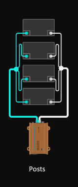
If you want to ensure the voltage at each battery is as identical as practical, you would create all of the battery cables to be exactly the same length, crimp the lugs to the cables, solder the lugs to the cables to reduce the crimp-based resistance differences, torque all of the bolts holding the lugs to the battery terminals to the same pressure and then connect them like this:

1658492177372.png
 
Back
Top