diy solar

diy solar

How to solve N/G bond problem with my cheap AIO ?

What I understood. I am not electrician!

You have normally PE ( Ground ) and N - bonded ( connected together ) at AC grid input. When AC grid switched OFF ( goes to battery+ solar mode = OFF grid without AC connected ), by inverter! (not by power loss ) using internal realy of inverter the you lose the PE+N bonding ( arriving from grid ). This makes the 2 main issues mentioned, no neutral reference output so you can measure on inverter output 110V between N and PE ( ground ) etc... Second issue is protection for RCB ( they argue here is not issue as there is no contióunitiy anyhow ) All together there are risks we want to avoid!

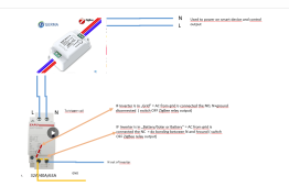
Do not connect N Input and N Output. You need to find a way to connect N output and PE( ground ) when inverter switches OFF the grid - automated bonding for N output and PE.

You need to use AC modular contactor switch to create PE+N ( bonding ) when your inverter disconnect grid input AC ( L and N ) and goes battery mode.

Contactor type: 2 P ( same ampere as max of inverter or higher ) AC modular contactor switch controller, Some are DIN rail mounted and have small led when contactor is in NC mode! ( ~15 USD ). If you ask me one that is NC ( see explanation below ).

I have EASUN inverter ( SML III 5 KVA ) I need to find the relay(inside inverter ) or on circuit board place where when switches OFF the grid ( L and N ) then the modular switch mentioned will disconnect the PE+N ( bonding ). Some inverter may have small relay output already but not most of EASUN inverters.

So if you ask me the relay must be NC ( Normally closed ) = "N output" and PE connected, then when AC from grid switches ON ( N and L ) - then is opening = interrupt the "N output" and PE. Remember "N input"(grid ) and PE is already connected.

I read here just connect to relay( the used for bonding ) the L input from grid, yes BUT the L input from inside the inverter after the inverter internal relay switch. If you connect the L input from grid just before the inverter this will always have current, as the disconnection happens inside the inverter own internal relay switch.

Anyone to confirm am I correct ? Does anyone identified this in EASUN inverters: also keeping in mind that the 3KW and 5 KW inverters from EASUN are different and different models but they all have internal relay!

thanks
 
RCD doesn't require a N/PE connection to work.
Agree I wanted to say MCB ( normal small 16/25/30 amp braker ). I have RCD( FI relay) before and after inverter---- yes bonding done before them not to pop them.
I also need to cover fluctuation in battery mode I have 220V , so 120V between earth+ N and 100V for L+N . I don"t like it.
On EASUN 5000KVA ( SML III ) I tested it in battery mode+ solar ( grid was switched off by inverter ) as soon as I connect N to ground all goes well, N+ground = 0V and L+ground=220V, L+N = 220V. then clearly testing conductivity for L+ground is there ( bonded )
Is generally the direction of heaving relay the good direction: Basically shift the P+N bonding.

Does anyone done it for EASUN inverter mainly SML series ??
Idea or anything like this, Maybe other 4 way relay switch to avoid opening inverter - thinking here that in grid mode, N(grid ) + ground are connected ( NC ) in grid off same for output BUT N (Out form inverter )+ground is not connected in off grid ? is not is there any relay logic that can be build on this ?

Thanks
 
Last edited:
One way to do it is to use SmartHome - I already have to detect Inverter mode
Inverter mode: Grid - - means is getting also power from grid + solar + battery ( but battery is depleted). Means grid incoming is connected.
Inverter mode: Solar/battery - is true off grid and grid incoming is switched OFF.

I can add a "smart" relay - mean I can drive it via ZigBee2MQTT, to switch PE(ground)+N between modes where N = grid for "grid" mode and N = output inverter for "solar/battery" mode.

This means I rely on my smart home to do the job.

Just as an option, but I still would rely on a hard wired device industry proof as smarthome depends on a lot of things.

1675713401362.png

1675713270001.png
 
I will do this most probably. no need to open inverter and do stupid things. Also using home-assistant I can manage / monitor / bring alert to my mobile and see historical values / eventually cut off power in case something goes wrong. Please note, I say this as I already use home-assistant as smart home to turn and control heating when we have sun.. get maximum of sun power - as many other things

what do you think ?
1675715540475.png


OFF topic: As example today was sunny day and heating house from PV

1675715149112.png
 

Attachments

  • 1675715089225.png
    1675715089225.png
    152.7 KB · Views: 4
Last edited:
I thought of doing something similar, but using a microcontroller (connected to the RS485 port of the inverter) instead of a home assistant/similar software.

One thing that other members of the forum noted was that these types of solutions will probably not react fast enough, and this might cause a double N-G bonds, even for a few seconds. This might not be that critical, but if your grid supply has an RCD before the input to the inverter, this double bond might cause it to trip.

Look at another solution as suggested by @FilterGuy :
Post in thread 'EDITED TITLE: Why not common Neutral? What is dangerous about it?' https://diysolarforum.com/threads/e...-what-is-dangerous-about-it.53252/post-687032

This involves connecting the Neutral in to Neutral out to get the bond from the grid, when available. When not available, a normally closed relay will power down, creating the N-G bond on the output.

It's a sleek solution using simple components, but I am not sure a common Neutral is OK for all inverters.
I haven't tried this yet on mine, as I'm afraid to fry something...
 
I will do this most probably. no need to open inverter and do stupid things. Also using home-assistant I can manage / monitor / bring alert to my mobile and see historical values / eventually cut off power in case something goes wrong. Please note, I say this as I already use home-assistant as smart home to turn and control heating when we have sun.. get maximum of sun power - as many other things

what do you think ?
View attachment 133628


OFF topic: As example today was sunny day and heating house from PV

View attachment 133627
Is'n Blue Neutral and Brown is Line in Europe?
 
I thought of doing something similar, but using a microcontroller (connected to the RS485 port of the inverter) instead of a home assistant/similar software.

One thing that other members of the forum noted was that these types of solutions will probably not react fast enough, and this might cause a double N-G bonds, even for a few seconds. This might not be that critical, but if your grid supply has an RCD before the input to the inverter, this double bond might cause it to trip.

Look at another solution as suggested by @FilterGuy :
Post in thread 'EDITED TITLE: Why not common Neutral? What is dangerous about it?' https://diysolarforum.com/threads/e...-what-is-dangerous-about-it.53252/post-687032

This involves connecting the Neutral in to Neutral out to get the bond from the grid, when available. When not available, a normally closed relay will power down, creating the N-G bond on the output.

It's a sleek solution using simple components, but I am not sure a common Neutral is OK for all inverters.
I haven't tried this yet on mine, as I'm afraid to fry something...
Well, Thanks for your input
I plan to remove RCB that is in front of inverter and have there only MCB that already exist and SPD arrester - never know what is arriving form grid.
After the inverter is MCB (max inverter power 25A B series ) then RCB(25A, 30ma) and from there goes to house panel where other MCB(6/10/16 amp ) are going to different area if the house.

Incoming power from grid is hard wired and protected in protective pipes directly to a distribution box ( MCB + SPD + RCB ) then to inverter. So there almost no way to touch incoming grid cables. From distribution box to inverter is 30 cm from inverter below of inverter, also cables goes in protective pipes.

Risk based approach, is way I look at this.
1. Is not allowed by regulations to connect neutrals together. Law say you need to guarantee galvanic isolation between the inverter and grid in case of power loss, this must be automated in inverter. Also say in case error inverter must be capable to start secuerly ( staying off until human intervention verify the error or safe start) . This is what inverter does by internal relay when power is off from grid inverter internal relay disconnect, power company can do safe maintenance on line and in case of fault inverter can remain OFF. Inverter in case of over current/ under current/short is switching off then is securely starting - or remains OFF.
2. Connecting neutrals together may do some other things in case of error that is then moved to incoming grid. I let other debate but there is remaining risk. ( see point 1 too )
3. We do not know how inverter is made, in my case EASUN 5KA SML III - so may create damages - not when grid is on because then clearly N in and N out are "connected" inside inverter. I do not know what happens in case of a fault and inverter get some current on N when that is not supposed to be there. All together we do not know the inverter.

With 3 risks above I would think that heaving dual bonding for 2-5 seconds - only in case when Inverter return to grid - battery depleted - is lower risk then 3 mentioned above. When inverter moves to battery then 2-5 seconds will have no bonding and fluctuating N.
MCD+MCB +SPD and further smaller MCB still in place to protect. Also inverter has build in all kind of protections.

Maybe to avoid dual bonding, can be used to switch the ground for N in and N out.... then is a 3 way or 4 way relay needed. I need to look it up, then remaining risk is 2-5 seconds no bonding. In case of smart home solution failure ,... need to think it over.

I already have smarthome to maximize the solar capacity, monitor full inverter values, and heat house using many other sensors for power and temperature and smoke detectors and so on independent from this "normal" protective solution - again intended to drive heating in house.
 
Last edited:
Well, Thanks for your input
I plan to remove RCB that is in front of inverter and have there only MCB that already exist and SPD arrester - never know what is arriving form grid.
After the inverter is MCB (max inverter power 25A B series ) then RCB(25A, 30ma) and from there goes to house panel where other MCB(6/10/16 amp ) are going to different area if the house.

Incoming power from grid is hard wired and protected in protective pipes directly to a distribution box ( MCB + SPD + RCB ) then to inverter. So there almost no way to touch incoming grid cables. From distribution box to inverter is 30 cm from inverter below of inverter, also cables goes in protective pipes.

Risk based approach, is way I look at this.
1. Is not allowed by regulations to connect neutrals together. Law say you need to guarantee galvanic isolation between the inverter and grid in case of power loss, this must be automated in inverter. Also say in case error inverter must be capable to start secuerly ( staying off until human intervention verify the error or safe start) . This is what inverter does by internal relay when power is off from grid inverter internal relay disconnect, power company can do safe maintenance on line and in case of fault inverter can remain OFF. Inverter in case of over current/ under current/short is switching off then is securely starting - or remains OFF.
2. Connecting neutrals together may do some other things in case of error that is then moved to incoming grid. I let other debate but there is remaining risk. ( see point 1 too )
3. We do not know how inverter is made, in my case EASUN 5KA SML III - so may create damages - not when grid is on because then clearly N in and N out are "connected" inside inverter. I do not know what happens in case of a fault and inverter get some current on N when that is not supposed to be there. All together we do not know the inverter.

With 3 risks above I would think that heaving dual bonding for 2-5 seconds - only in case when Inverter return to grid - battery depleted - is lower risk then 3 mentioned above. When inverter moves to battery then 2-5 seconds will have no bonding and fluctuating N.
MCD+MCB +SPD and further smaller MCB still in place to protect. Also inverter has build in all kind of protections.

I already have smarthome to maximize the solar capacity, monitor full inverter values, and heat house using many other sensors for power and temperature and smoke detectors and so on independent from this "normal" protective solution - again intended to drive heating in house.
I think you have a point there, regarding regulations and safety of grid workers, if common Neutral is connected.
@FilterGuy what do thing of this (in regards to your common Neutral thread) ?

@Zsan I guess your solution to skip the main RCD and handle bonding dynamically, with an RCD on the output is probably the best solution for me too.
I have my inverter laying around for months now... Did some testing, but haven't installed it fully because of this issue.

I guess now all I have to figure out is the dynamic bonding part.

Thanks for your input.
I have my inverter running without battery connected. All is ready.
If inverter is always using grid you are fine - my inverter can work without battery and combine solar power and grid. Will always consume grid ( ~100W ) no matter of solar capacity this way does not feed back to grid ( off grid inverter with AC backup with a limiter ). Ia also triggering grid if consumption jumps to high and no PV can manage that.
and yes bonding done before inverter - but my inverter has internal bonding . Open yours and measure look at it.! since you can do it safely now not using it.
EASUN SML III 5KW
1675754483934.png1675754507867.png1675754673598.png

After I fix automated bonding I connect battery.
If you have the same type of inverter go for it then battery and bonding as next step. cabling and things take alot of time and need power outages ..etc.. In my case I had to build cble traces in tubes as inverter is in garage due to noise and no way I want power generator inside living area.
 
Last edited:
These are Inverter states: EASUN SML III 5KW . Actual status is indicated by arrow
1675796385960.png
 
As important point that happened today during test i did.

Was a sunny day the I decided to get inverter to SUB(solar/utility/battery ) - "UPS" - mode and connect battery to charge fully- I never tested it after i build it. All went well, the I decided to test RCB, tripped just fine ( bonding inside inverter on grid input ) and get grid ON / OFF , then PV ON OFF then grid and PV ON / OFF to see how inverter act.
When grid was off clearly I ha fluctuating N for the few minutes for the test and measuring and using tested says there in no ground and voltage between N+G (120V) . Clear was no bonding,

Issue: I have RasberyPI connected to RS232 port to get inverter data ( MQTT ) then move it to home assistant. For RS232 I used USB to RS232 ( BD9 ) adapter. Well the USB RS232 adapter and RaspberryPI went down.
For serial communication we have TX/RX and GND - I strongly believe GND - that is also GND of inverter - get some nasty thing into the USB RS232 GND that fried the adapter/ was super hot. I replaced the USB RS232 and goes well now. I shuted down the battery - disconnected.

So fluctuating N will produce damages, therefore I decided to have RS232 surge protector between inverter and the PI when building the automated smarthome bonding for off grid.
Hope it help others.
Was the inverter ground in any way at the time? If you removed ground to the inverter when disconnected from grid, thats not good.
 
Yes, inverter was connected to ground. same as inverter case / this is done internally from GND input ( see pictures above post) .
It is highly recommended to have BD9 surge protection( isolator ) even is you choose to use GND box for inverter.


My strong assumption: This device is exactly what I described above - using using microelectronic ( i would do it with nanoPI and (2)4 way was relay ) - getting inverter sate from serial can bus.
EDITED: they use AS400 is there in documentation
1675931068434.png

I want to do this with MQTT because ( on RasberryPI) I wan to use all inverter values for smart home. Only "issue" is that using box is process driver - response time sub 10ms - where out of MQTT protocol you get 1-2 s delay in case you have huge smarthome max 5s to make bond switching.

Eitherway I recommend RS232 surge protector ( isolator ). - is ajust a few $$$ to protect a high value and important safety process.
 
Last edited:
Yes, inverter was connected to ground. same as inverter case / this is done internally from GND input ( see pictures above post) .
It is highly recommended to have BD9 surge protection( isolator ) even is you choose to use GND box for inverter.


My strong assumption: This device is exactly what I described above - using using microelectronic ( i would do it with nanoPI and (2)4 way was relay ) - getting inverter sate from serial can bus.
View attachment 134018

I want to do this with MQTT because ( on RasberryPI) I wan to use all inverter values for smart home. Only "issue" is that using box is process driver - response time sub 10ms - where out of MQTT protocol you get 1-2 s delay in case you have huge smarthome max 5s to make bond switching.

Eitherway I recommend RS232 surge protector ( isolator ). - is ajust a few $$$ to protect a high value and important safety process.
I have seen this grounding box before.
The problem is that is relies on a dry contact relay, to switch on when inverter is in off-grid mode.

While many inverters have this dry contact, it only works as a low battery relay (like to power a generator to charge the batteries).
This could probably be changed in firmware, and older models actually have the option to set the working mode of the dry contact. For some reason they removed this option in newer models/firmware.

I don't see where you can plug in the AS400 card that they recommend to use in our inverters, either.
AS400 is inside the box, to the serial port of your inverter. all inverters arrive with WIFI you plug to inverter ( chinese once ) - and and RS232
I read personally use serial port of inverter all values. ( MQTT )

1675936341152.png1675936353142.png


all you need here is the power cables the rest is "ut of the box ( in the box ) , plug and play...
Right, not using dry contacts ?
EDITED: Yeah maybe is dry contact----- AS400 can have communication interface then we are back to read serial port like I do then here... so .. well. Based on firther documentation they wrote I assumed there is RS232-485 inside to ASIbus then they set firmware to read then do magic.. Naive thinking. I will buy one just to see it inside is fairly cheap. Then I remain original idea smart home to manage this. I am waiting for realy and zigbee device to arrive then I will set them up and update here community.
 
Last edited:
I need a bit of help here.
So I play around with abit and this is what is in the EASUN SML III 5KWA inverter on AC INPUT.
AC output is straight forward.

1676117423458.png1676117443804.png

1676117476807.png1676117524835.png


MKP62 Capacitor: Suppress electromagnetic interference from the power supply.
So only on INPUT ( grid ) : between N and L is this capacitor.
Between N and GND is that "fuse something" ( Impedance ? )
Between L and GND same "fuse something" but inverted "polarity" ( Impedance ? )

Is this how they do bonding of N and GND - or is just to suppress on input side any electromagnetic interference.
Thanks

EDITED: Maybe is this ? ( I understand but does not tell me anything )

Variable Virtual Impedance-based Overcurrent Protection For Grid-forming Inverters​

 
Last edited:
I need a bit of help here.
So I play around with abit and this is what is in the EASUN SML III 5KWA inverter on AC INPUT.
AC output is straight forward.

View attachment 134299View attachment 134300

View attachment 134301View attachment 134302


MKP62 Capacitor: Suppress electromagnetic interference from the power supply.
So only on INPUT ( grid ) : between N and L is this capacitor.
Between N and GND is that "fuse something" ( Impedance ? )
Between L and GND same "fuse something" but inverted "polarity" ( Impedance ? )

Is this how they do bonding of N and GND - or is just to suppress on input side any electromagnetic interference.
Thanks

EDITED: Maybe is this ? ( I understand but does not tell me anything )

Variable Virtual Impedance-based Overcurrent Protection For Grid-forming Inverters​

That's just a line conditioner. Think of it as a filter.
It has nothing to do with bonding.
 
Something that did go over my mind as reflection.

Fact: N Input and N output ( same for L ) are connected together inside the inverter by the inverter internal switching relays.
For testing only: I disconnected the GND from inverter and switched OFF the power input from grid - I have 40S, 3 channel power switch. I let only solar input. There was no continuity between N input and N output. As soon as I switched back the grid input, Immediately I heard relays switching inside inverter and had perfect continuity between N input and N output ( perfect beep - no current ). So is clear inverter connects N input and N output internally when in "Grid" mode. ( same for L )
Then I connected all back ( GND and so on ). - safety is critical.

Connecting Neutrals together seems to be a normal thing as anyway the inverter is doing this. Then your problem is solved.

Now how the issue
1. About being law compliant that say when grid is OFF ( for maintenance ) you need to guarantee galvanic isolation.
2. In "Solar/Battery" mode = N input and N output is disconnected by inverter internal relay ) : if you get some nasty thing arriving over in the N from grid( explained below ) if you connected N together outside the inverter.

1676187377671.png

What is the difference except graphical representation between above when you use jumper for N in and N out and using jumper from GND to N
what is different between this 3 representations for same ( except graphic ? ), this is why even some inverter manufacturers tell you connect N's together will solve your issue. Yes, but not the above mentioned other 2 issues

1676187463347.png1676187478300.png

Depending in graphical representation for above picture some call is dual bonding but if you "just connect N" is fine ?.

So actually is this (below ) what we should have, 2 way relay switch. Is more closer to the derived independent 2 power sources. You can switch either N or GND in picture below is just graphical representation.

1676187808663.png

and switch to Solar/Battery mode
1676187834273.png


My conclusion:
Option A:
You can connect N together ( depends inverter - verify first ) - you solved issue of bonding N-E and fluctuating N in "Solar/Battery" mode but have 2 remaining issues
1. Law compliance
2. Nasty current from grid - will an SPD at grid input protect ? I think yes.

Option B: As pictures above get relay to switch N-E ( either N or E ) then all issues solved, but in some cases not easy to do,

What do you think?
 
Last edited:
Back
Top