diy solar

diy solar

How to wire a DC breaker?

think Midnight wired them in series, both same polarity, so two 150V polarized poles serve as 300V polarized.
The suggestion is to reverse polarity of one, so it works as 150V non-polarized.
I was reading it that ‘in’ on one was protecting in the direction of battery, while ‘in’ on the other was protecting in the direction of SCC… but the idea of one not disconnecting due to an internal ‘wrong-direction’ arc and cross-shorting I can visualize as well.
 
Does that mean 3x PV positive home-run wires but only one PV negative? For some SCC (Renogy, automobile application) PV negative is ground. But for most, it is required to be separate. So I think should be 3x PV positive and 3x PV negative, all isolated.
Yeah, the PV runs all have been planned for separate negative wire runs too (I bought all the red and black wire for the full runs).

I'll have to check the manual and see if MPP LV6548 should have isolated PV negative or not. I wonder though, if it is supposed to be isolated, perhaps one could have some kind of small bleed resistor from PV negative to Earth ground to keep PV negative from possibly floating without negatively affecting the circuit (if there was any potential of that occurring).

I could just check to see with a voltmeter when the positive is disconnected, to see if there is any actual voltage between PV negative and Earth ground, and if not, then not worry about it. This more of a quick disconnect in the PV run for firemen or emergency shutoff... If positive is disconnected then the PV circuit is definitely open.

Midnight 4x 150V polarized for 300V non-polarized?
I didn't spot that with a quick scan. There was a 2-pole 300V non-polarized, assume that's made from 150V non-polarized poles.

I guess it would be a 4x (DIN) 600v (reconfigured with a bus bar on each pair, 2x each breaker in series, use one pair for positive and one for negative), to have both conductors disconnect and be a 300v rated disconnect.

When I get to the actual installation piece of it, I will look at all this stuff with a lot more detail, just went on the best information I had at the time, and I would've bought a bigger box had I known, but got the 6 DIN box due to budgetary constraints.

Maybe I'll just put a pair of wire clippers in a fire extinguisher box outside the hose with a large sign saying, "Attn: Fireman, to kill power, cut the cords below using these insulated sheers"...
 
Last edited:
But I'd rather have a non-polarized one.

The specs for the one you found do seem better. Non-polarized. Also 500V. (Although a chance that means 500V for 2 poles, and the other one from Schneider might have been 250V per pole, same thing.)
Thanks a ton. I think I'll return the other 2 I already got, and switch to those non-polarized.
 
I'll have to check the manual and see if MPP LV6548 should have isolated PV negative or not.

I checked in the MPP LV6548 manual, and it says the inverter is non-isolating, so negative of PV circuit should have the same potential as Earth ground. The panels still should still not have the negative run grounded (since it will be already grounded inside the inverter (don't want leakage to occur between two ground points), but the potential on the negative PV wire should always be the same as ground, so there is really no need to disconnect negative on the PV circuit using the disconnect switch (no need to waste 2 DIN slots in the box for a negative). At least that's how I see it. I can check it with a DVOM to make sure...
 
Last edited:
But if the breaker rated for your voltage requires two poles in series, you can either run PV positive through both, or PV positive through one and PV negative through the other. Same real estate occupied.

Breaking both wires, you can disconnect the MPP for service. Breaking just one, you might worry that a short or even just leakage could drive the negative wire to high voltage as soon as inverter is disconnected.

So I'm just wondering, why do they sell it that way with the bus bar in there, to bridge the 2 in series, if you could just wire it that way you indicated? It seems easier and more foolproof to do it like you said (makes sense it would work though, they're still both in series, just in different places in the circuit)...
 
Last edited:
Each breaker handles 4s2p panels (8 panels, about 21.18a Isc)... 3 independent PV runs into the inverters (24 panels total).

These 300v 30a breakers I purchased from Midnite Solar are actually 2 single-pole breakers connected in series with each other (wire goes in on top-end, while bottom-end of breaker has a little bus bar connecting to the other breaker siamesed onto it, then the other wire connects to the adjacent breaker on the top-end.

So no wires hook to the bottom of the breaker, just has the copper bus bar.

I'm going to bump this....

i ordered an NMEPV50-300 -- https://windandsolar.com/midnite-solar-mnepv20-300-breaker/

I was planning to break both the - and + by removing the bottom copper bus bar, but sounds like that only gets me to 125v/25a. on the sticker on the side it says "Ue: 125v dc" or "Ue: 250v dc 2P in Series"

so, to get the 300v/50amp I am only going to break the + PV load? and I need to order a second 2P in series breaker for the negative?
 
You do not need to “break” the negative side, there is no reason to do so.

On those coupled DC breakers it is not pratical to try to make two breakers out of the one. Many of those are only rated at 1/2 the total voltage and one side is reversed in polarity.

It is most important to have the breaker polarity correct......Most positive voltage ( source) (the solar panels) to the positive post and least positive (load) to the negative for the solar array .

The breakers for the charge controller is wired +(positive) to the battery, and - (negative) to the charge controller which seems backwards as the charge controller voltage is higher than the battery BUT.....that is in “Non Fault“ mode. When the controller has a short the battery is the source......the “most positive” and current flow will be from the battery to the controller
 
Many of those are only rated at 1/2 the total voltage and one side is reversed in polarity.

It is most important to have the breaker polarity correct......Most positive voltage ( source) (the solar panels) to the positive post and least positive (load) to the negative for the solar array .
yes, that's how it appears exactly. thank you.
 
Nothing's easy!

Here's the breaker I'm trying to wire up; CHTAIXI Breaker

Problem is.....I can't figure out which side in the Source (power side) and Load side (device DC is being sent to)

'You have any idea?
Well shucks , yer problem is simple , no one can pronounce the name on that thing… only buy things that have readable names….?
 
All ungrounded conductors in any circuit are required to be opened (disconnected, broken) by a common handle.
I am referring to American gear, I do not use Chinese, All my inverters and controllers are made in America for use under UL , AND all are “listed” to UL1741

None of my American Inverters and Controllers recommend switching the <EDIT...strike neutral, I meant negative>

High frequency switch mode units (made offshore) are a horse of a different color,....

As a commercial electrician I would not touch any piece of equipment that has a Chataxi breaker

But then again in industry where I learned most of my skills we never, never ,never used Chinese parts

Huge American Corporation known by a 2 letter symbol........
 
Last edited:
A neutral is a grounded conductor.
"All ungrounded conductors are required to be opened by a common handle."
Ok wrong word there, I meant negative not neutral.....this is DC...there is no neutral , neutral happens with 120/240 split phase

No the P.V. negative is not grounded on Midnight.......There is a Arc fault and Ground fault in there.....Grounding the negative defeats the AFCI and GFCI

Same with Schneider’s modern stuff

I don't touch Chinese except to rip it out when red tagged by our local building department,


They are real tough about “LISTED.....to UL1741”

Chinese Stuff “Tested to U.L. “ doesnt get it here ....Automatic red tag.....Remove it or we will remove your power

I have several off shore units in my junk pile, some never used that didn't pass code
 
Last edited:
On DC breakers, + means the more positive potential across the breaker and the - means the more negative potential across the breaker when the breaker is closed with current flowing (imagine there is some resistance in the breaker contact, which there is). This gets the current flow in the correct way so the internal magnet flares the arc in the desired direction to best extinguish the arc when breaker is opened.

The particular breaker shown is a double pole DC breaker. It is intended for HF inverters, and transformer-less GT inverters that do not have electrical galvanic isolation between the PV lines from their AC output side. You have to use a double pole breaker for breaking both PV pos and neg lines to avoid possibly leaving AC riding on one of the PV lines.

The double pole parallel breakers are designed so the desired current flow is reversed between left and right-side breakers. + would normally go to PV panel positive wire and - would normally go to negative PV panel wire.

Besides breaker terminal polarity, many DC breakers use orientation to flare the hot plasma arc upward (heat rises). You should always mount DC breakers so the text on breakers is upright correct reading. Not upside down or on their side.
 
Last edited:
Ok wrong word there, I meant negative not neutral.....this is DC...there is no neutral , neutral happens with 120/240 split phase

No the P.V. negative is not grounded on Midnight.......There is a Arc fault and Ground fault in there.....Grounding the negative defeats the AFCI and GFCI

Same with Schneider’s modern stuff

I don't touch Chinese except to rip it out when red tagged by our local building department,


They are real tough about “LISTED.....to UL1741”

Chinese Stuff “Tested to U.L. “ doesnt get it here ....Automatic red tag.....Remove it or we will remove your power

I have several off shore units in my junk pile, some never used that didn't pass code
If the positive and/or the negative are not grounded. Then, they are required to be switched.
 
If the positive and/or the negative are not grounded. Then, they are required to be switched.
Really,

try telling that to boB Gudgel at Midnight Solar

or maybe Robin Gudgel at Midnight Solar....

or Andy at Midnight Solar


Thanks for your interpertation any way. I have had Midnight Solar since they were introduced...4 systems all with non switched negative....All with Midnight Solar PV combiners which do not switch the negative

2 each Midnight Classic 150’s with Midnight PV-6 combiners with built in AFCI and GFCI
2 each Midnight Kid with shared split Midnight PV-6 combiners with external GFCI and AFCI

All wired exactly as specified by Midnight Solar

All passed by my inspector

Before Midnight was incorporated I had Trace Inverters and Trace PWM controllers , again non switched negative......

Try telling that to Trace...........no negative switching..........Again Robin and boB Gudgel.....

Try telling that to Outback Solar......no negative switching.........Again (founded by) Robin and boB Gudgel

Try telling that to Schneider Electric’s solar division....no negative switching.......Again (original company founded by) Robin and boB Gudgel


In any case you do provide some valuable information and I do appreciate it

I started doing solar in 1966......long before MPPT.....long before PWM..
I powered two way radio sites on mountain tops for industry.....this is “MISSION CRITICAL” infrastructure 24/7/365
law enforcement, fire, muni services, army, air force, US Govt communications, etc.

By the way.......Solar as we use it was developed and patented by the Communications Industry to power communications systems

Surprise...........American Telephone and Telegraph patented the monocrystalline solar panel in early 1950’s to power communications sites


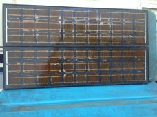
I’m no newbie to Solar.....pic’s below of some panels I installed on Blue Ridge for a repeater system in the ‘60’s
note extremely rare 33 cell “self regulating” panels for use with no controller

I retired from a major American corporation who is huge in electricity........known by two letters...all over the world


Anyway appreciate your input but you are misinterpreting the code
 

Attachments

  • 9013E04B-7F09-498E-9642-AA495230E69E.jpeg
    9013E04B-7F09-498E-9642-AA495230E69E.jpeg
    829.2 KB · Views: 3
Last edited:
Back
Top