Hello all...
Sorry for this post....I came back to the top and added this line as I could see i was rambling. I am basically looking to see if there is a way I can rewire/improve how I am doing stuff with little or no cost..
I'll put a post up just to say a quick hello, but already, by doing the 'new to a forum' things, like reading FAQ's I have answered my own question, or at least confirmed what I thought.
Bit of a mixed post this, see if any one can pick their way through my ramblings.
I live in Jersey, the island, 49.17 Degrees North, 2.05 West.
I'll summarise here, just in case any one has any bright ideas.. Though I'll not be spending any money again for a while as I just upped my mortgage from £700 a month to £1900...my choice...pay it off quicker..so no new toys for a while
Unless of course someone can recommend I a worthwhile, but cheap (£120-150 max) MPPT controller upgrade that will give a great improvement over the PWM
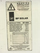
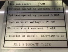
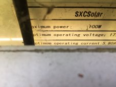
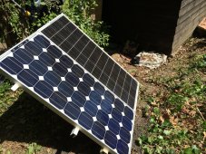
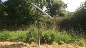
I inherited a pair of unmatched panels and a Sun YOBA® 80A controller. It does its job ..cant say more than that. Suspect it to be a cheap and cheerful thing, probably no the most efficient...but as I say it was all free..inherited from a chap i helped in his last years of life. I do suspect it might be junk..but no idea ..wont take offense if you all laugh at it, and say it came from a Christmas Cracker
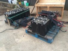
Battery bank is 2volt lead acid cells..big things, 6 x4 inch by 18 inch tall roughly, from an aircraft tug, about 4 tonne of them. I rigged them up about 4 years ago. and I cant give the exact series parallel config at the moment, but I think 4 parallel strings of 6 to give 12 volt out. I had a 12 volt 2kW 240volt inverter, so had to go with 12 volt.
They are not matched as you can see
they are wired in parallel
about 60 foot from the controller.
Cable is 4 core Flexible 3 phase armoured industrial/farm machinery type flex. Since 4 core, the cores are paired to give lower resistance.
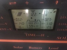
Bright sunlight, the controller shows a max of 8 amps. I can turn the panels manually during the day to keep them aligned. This is al set up in a farm meadow /camping area to supply us with WiFi/Sonos connectivity to the house, lighting etc for the odd nice summer day we can use the area. If you are in the UK you will know it has not had much use this year!
years ago when I rigged it up, I just did them in parallel and just left it . it works..it is fine...but if the power is left on, and we get cloudy conditions, the battery bank does drop slowly over a week or two to about what can be seen in the controller picture.
Got to thinking about it the other day and thought I might get improvement / less voltage losses if wired in series. Controller is good for < 48 volt and it does run fine wired in series.
But it is a PWM controller...so a higher voltage in and half the current. yes I checked this the other day . from 7.9 amps down to 3.3 amps when in series..as expected higher voltage too..but only till the charge controller does its thing.
So what do you all reckon ...would a MPPT controller and wire in series make a good noticeable difference..like 30-40 % or more or is it going to just be a marginal increase?
No money or time or inclination to buy new panels yet, just makign the best of what we have with the thought to leave it on 24/7 drawing 2-3 amps for inverter, WIFI Bridge and AP and a CCTV camera.
If I could squeeze another 30-40 % charge capacity to keep the batteries topped up , i reckon all would be good to keep it powered permanently.
Sorry for this post....I came back to the top and added this line as I could see i was rambling. I am basically looking to see if there is a way I can rewire/improve how I am doing stuff with little or no cost..
I'll put a post up just to say a quick hello, but already, by doing the 'new to a forum' things, like reading FAQ's I have answered my own question, or at least confirmed what I thought.
Bit of a mixed post this, see if any one can pick their way through my ramblings.
I live in Jersey, the island, 49.17 Degrees North, 2.05 West.
I'll summarise here, just in case any one has any bright ideas.. Though I'll not be spending any money again for a while as I just upped my mortgage from £700 a month to £1900...my choice...pay it off quicker..so no new toys for a while
Unless of course someone can recommend I a worthwhile, but cheap (£120-150 max) MPPT controller upgrade that will give a great improvement over the PWM
I inherited a pair of unmatched panels and a Sun YOBA® 80A controller. It does its job ..cant say more than that. Suspect it to be a cheap and cheerful thing, probably no the most efficient...but as I say it was all free..inherited from a chap i helped in his last years of life. I do suspect it might be junk..but no idea ..wont take offense if you all laugh at it, and say it came from a Christmas Cracker
Battery bank is 2volt lead acid cells..big things, 6 x4 inch by 18 inch tall roughly, from an aircraft tug, about 4 tonne of them. I rigged them up about 4 years ago. and I cant give the exact series parallel config at the moment, but I think 4 parallel strings of 6 to give 12 volt out. I had a 12 volt 2kW 240volt inverter, so had to go with 12 volt.
They are not matched as you can see
they are wired in parallel
about 60 foot from the controller.
Cable is 4 core Flexible 3 phase armoured industrial/farm machinery type flex. Since 4 core, the cores are paired to give lower resistance.
Bright sunlight, the controller shows a max of 8 amps. I can turn the panels manually during the day to keep them aligned. This is al set up in a farm meadow /camping area to supply us with WiFi/Sonos connectivity to the house, lighting etc for the odd nice summer day we can use the area. If you are in the UK you will know it has not had much use this year!
years ago when I rigged it up, I just did them in parallel and just left it . it works..it is fine...but if the power is left on, and we get cloudy conditions, the battery bank does drop slowly over a week or two to about what can be seen in the controller picture.
Got to thinking about it the other day and thought I might get improvement / less voltage losses if wired in series. Controller is good for < 48 volt and it does run fine wired in series.
But it is a PWM controller...so a higher voltage in and half the current. yes I checked this the other day . from 7.9 amps down to 3.3 amps when in series..as expected higher voltage too..but only till the charge controller does its thing.
So what do you all reckon ...would a MPPT controller and wire in series make a good noticeable difference..like 30-40 % or more or is it going to just be a marginal increase?
No money or time or inclination to buy new panels yet, just makign the best of what we have with the thought to leave it on 24/7 drawing 2-3 amps for inverter, WIFI Bridge and AP and a CCTV camera.
If I could squeeze another 30-40 % charge capacity to keep the batteries topped up , i reckon all would be good to keep it powered permanently.