In my limited experience, Alodine isn't very durable.Would Alodine work well enough?


You are using an out of date browser. It may not display this or other websites correctly.
You should upgrade or use an alternative browser.
You should upgrade or use an alternative browser.
Improving Contact Area on Welded Stud Pads
- Thread starter Horsefly
- Start date
Hedges
I See Electromagnetic Fields!
- Joined
- Mar 28, 2020
- Messages
- 20,682
I made up welding wire with soldered terminals for a jeep winch, way back when. It worked well enough, but now in retrospect, had those lugs over-heated and the cable let go, it could have been a helluva mess.
I don't think soldered is a contact resistance issue. Copper (e.g. cold welded) would be lower resistance and better, but solder performs well at least with a thin bond line. Now if you put a 2 awg wire in a 4/0 terminal filled with solder, the higher resistance of solder might make it have lower ampacity (before melting!) than a good connection.
I think the problems with solder on stranded wire is corrosive flux trapped inside (obviously no-clean flux isn't so bad, especially if heated until it passivates), and solder wicking in and making a stiff section that can lead to mechanical damage. Flux normally melts, activates, clean the metal surfaces, dries out as volatile materials evaporate. After solder reflows and cools, the remaining flux forms a passivating surface. But with stranded wire I would expect it to wick up so far that part of it doesn't drive off the solvents.
Maybe soldering only the toe of a crimped connection would minimize what goes up strands under insulation.
70/30 solder 0.185 micro-ohm meter

copper 1.68×10^−8 ohm meter, 0.0168 micro-ohm meter, 10x better than solder
:max_bytes(150000):strip_icc()/CircuitBoard-58c965fd5f9b58af5c86a992.jpg)
A Table of Electrical Conductivity and Resistivity of Common Materials
This table of the conductivity and resistivity of many common materials will help you learn about the concepts and factors that affect conductivity.
So solder would dissipate 10x the power, get 10x the temperature rise (if formed in same diameter conductor for a long length). Solder cup probably provides much larger "cross section" as current spreads in all directions so might not overheat. Poorer thermal conductivity would cause more temperature rise in the middle, half way between wire and terminal. I could imagine a test, increase current through cable & terminal while performing a pull test.
ericfx1984
Solar Enthusiast
- Joined
- Oct 10, 2021
- Messages
- 741
At least you don't have to deal with these I suppose the advantage is the stud is removable and you have a fairly large threaded area.. what I am planning to do with these is rather similar to what you've done I think I will do one around the bottom and then a large riser to go around it it's certainly not ideal but I think it will increase quite a bit

Have you guys looked at the paths and connectors to the components on your bms?
A solid connection is way more important than surface area, and adding ill fitting washers or weird hacks to pad the terminal does more damage than good. Even if you get a good low resistance connection now, it will have a lot more issues down the road.
There are lots of high current pcbs with surprisingly small traces, because the are short and have solid connections to the components.
hwse
Solar Enthusiast
- Joined
- Jan 2, 2021
- Messages
- 585
I am sitting here wondering why there would be and polychlorinated biphenyls in a LFP battery system because they were banned decades ago....There are lots of high current pcbs with surprisingly small traces, ...

D'oh! PCB stands for printed circuit board.
Must be a generational thing.Have you guys looked at the paths and connectors to the components on your bms?
A solid connection is way more important than surface area, and adding ill fitting washers or weird hacks to pad the terminal does more damage than good. Even if you get a good low resistance connection now, it will have a lot more issues down the road.
There are lots of high current pcbs with surprisingly small traces, because the are short and have solid connections to the components.
We did not install an 'ill-fitting' washer, nor a weird hack. There was no damage. And the connection IS solid.
Explain where ANY of that applies. Galvanic corrosion was as big of a consideration as surface area. Copper to aluminum just isn't recommended.
triplethreat
Solar Enthusiast
- Joined
- Oct 12, 2021
- Messages
- 129
Ill fitting????? Those washers fit like socks on a rooster!I am sitting here wondering why there would be and polychlorinated biphenyls in a LFP battery system because they were banned decades ago.
D'oh! PCB stands for printed circuit board.
hwse
Solar Enthusiast
- Joined
- Jan 2, 2021
- Messages
- 585
I think you quoted the wrong post. I was making a joke about what a "pcb" is.Ill fitting????? Those washers fit like socks on a rooster!
At least you don't have to deal with these I suppose the advantage is the stud is removable and you have a fairly large threaded area.. what I am planning to do with these is rather similar to what you've done I think I will do one around the bottom and then a large riser to go around it it's certainly not ideal but I think it will increase quite a bit
View attachment 83939
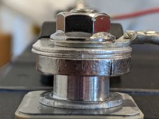
These are the same thing I have, same 230A cells. Get a set of the washers from @triplethreat. They fit perfectly and double the contact area without mixing metal compounds - aluminum to aluminum. Put your tin-coated busbars on top.
The serrated SS nuts that came with the cells are probably fine, but I would have much preferred SS nylocks. I locktited the grub-screws into their sockets.
Last edited:
triplethreat
Solar Enthusiast
- Joined
- Oct 12, 2021
- Messages
- 129
I did.....the wife was yelling that dinner was ready and I lost all sense of anything going on.....except to get to the table before the kitchen closed!I think you quoted the wrong post. I was making a joke about what a "pcb" is.
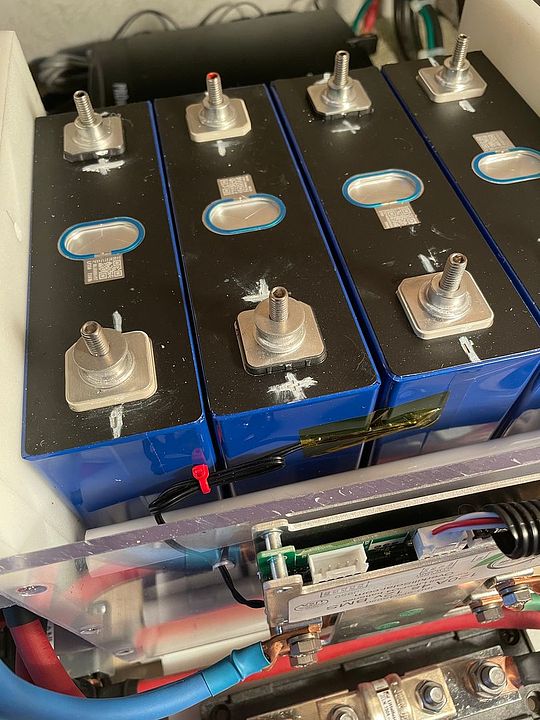
Without improving the contact area by adding conductive washers around the outside diameter of the Eve 230 AH threaded posts, I have just run a 4-minute test at 150A continuous load into an Inverter. I must note right away that my bus bars are really great, more than 2.5x the cross-section of the pathetic "double thin ones held together with shrink wrap" which I received for free from Docan (shown here.) For each of my 3 bus bars, I stacked the Docan-supplied thin pair above a single better one, built for 270 Ah cells by a different forum member.
Because the "better" ones were drilled with slots at greater distance from each other, I had an opportunity to drill a new hole (in order to fit the Eve 230 cells widths). I made those new holes completely round and only 6mm in size. These better bus bars lie directly on the threaded terminal cylinders, with 100% cylinder coverage surrounding my new hole and about 75% coverage surrounding the other one (at the end of the oppostive pre-drilled slot.). These are all pressed into the "terminal cylinder" by the nut on top of the threaded terminal post. Each threaded post was torqued into the terminal assembly at 50 inch-pounds before adding the bars, washer, and nut. Then I toruqwes the nuts up to 70 inch-pounds, just 12% short of their rated maximum value. (The bottom "better" bars are pressed directly into the terminal "cylinder" posts, with no intervening washer. On each post, a washer is present between the nut and the Docan supplied "thin pair".)
With that thoroughly explained, I also cut off the "B -" terminal lug on my Daly BMS (200A). That terminal lug had a big center hole, it may have been even bigger than 8mm (5/16), and would have done a terrible job of contacting the post (needing washers on both sides). I replaced it with a new lug, hole size 6mm (1/4") to fit directly on the cylinder without any added washer. Although advertised by Daly as "AWG 2" on the insulation, the wire sizes of "B -" and "P -" on my Daly were bigger, very close to AWG-1.
My 12v power lug (for wire size AWG 2/0) has the same hole diameter.
- - -
I did not take the time to create a 200A load, but I found NO warming on any of the terminals over a 4-minute period at 150A. Either the "heat" was being pulled into the packs (and I felt no warmth of my steel compression pates either), or the resistive power loss was very small. Up to at least 150A, with tight bus bars and load wire lugs, the 230A Eve terminals are having no problem.
Last edited:
100 Proof
"Please Lord, don't let me do something stupid."
- Joined
- Feb 14, 2021
- Messages
- 206
Pictures?Without improving the contact area by adding conductive washers around the outside diameter of the Eve 230 AH threaded posts, I have just run a 4-minute test at 150A continuous load into an Inverter. I must note right away that my bus bars are really great, more than 2.5x the cross-section of the pathetic "double thin ones held together with shrink wrap" which I received for free from Docan (shown here.) For each of my 3 bus bars, I stacked the Docan-supplied thin pair above a single better one, built for 270 Ah cells by a different forum member.
Because the "better" ones were drilled with slots at greater distance from each other, I had an opportunity to drill a new hole (in order to fit the Eve 230 cells widths). I made those new holes completely round and only 6mm in size. These better bus bars lie directly on the threaded terminal cylinders, with 100% cylinder coverage surrounding my new hole and about 75% coverage surrounding the other one (at the end of the oppostive pre-drilled slot.). These are all pressed into the "terminal cylinder" by the nut on top of the threaded terminal post. Each threaded post was torqued into the terminal assembly at 50 inch-pounds before adding the bars, washer, and nut. Then I toruqwes the nuts up to 70 inch-pounds, just 12% short of their rated maximum value. (The bottom "better" bars are pressed directly into the terminal "cylinder" posts, with no intervening washer. On each post, a washer is present between the nut and the Docan supplied "thin pair".)
With that thoroughly explained, I also cut off the "B -" terminal lug on my Daly BMS (200A). That terminal lug had a big center hole, it may have been even bigger than 8mm (5/16), and would have done a terrible job of contacting the post (needing washers on both sides). I replaced it with a new lug, hole size 6mm (1/4") to fit directly on the cylinder without any added washer. Although advertised by Daly as "AWG 2" on the insulation, the wire sizes of "B -" and "P -" on my Daly were bigger, very close to AWG-1.
My 12v power lug (for wire size AWG 2/0) has the same hole diameter.
- - -
I did not take the time to create a 200A load, but I found NO warming on any of the terminals over a 4-minute period at 150A. Either the "heat" was being pulled into the packs (and I felt no warmth of my steel compression pates either), or the resistive power loss was very small.
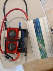
Sure. Here's one of my "triple stack" bus bars, and a picture of my Inverter test configuration. I'm replacing the thin and warped compression plates, moving up to 1/4" steel as I used in my previous battery packs.Pictures?
Attachments
Horsefly
Solar Wizard
While I don't necessarily disagree that you may be fine without improved contact area, I'm not sure a 4-minute test is long enough to really know if you have some increased resistance that might generate heat. You might want to try it for a bit longer to make sure.4-minute test
How were you checking the temperature of all the terminals?I found NO warming on any of the terminals over a 4-minute period at 150A
Are you saying that your bus bars are made of steel?I'm replacing the thin and warped compression plates, moving up to 1/4" steel as I used in my previous battery packs.
EDIT: My bad. I guess you are talking about the plates used for compressing the cells? Never mind then.
Last edited:
Having misplaced my finicky thermocouple based thermometer, I merely held my finger against a few of the terminals. I agree that to be very "loose" testing, with accuracy roughly 1 degree C. Bus bars are all copper, each built with extremely thin tin electroplate. Direct placement avoided lower conductivity of aluminum washers over the small area of the post cylinder tops, and also avoided "rust" issues with dissimilar metals (the "copper in contact with "aluminum alloy" issue).While I don't necessarily disagree that you may be fine without improved contact area, I'm not sure a 4-minute test is long enough to really know if you have some increased resistance that might generate heat. You might want to try it for a bit longer to make sure.
How were you checking the temperature of all the terminals?
Are you saying that your bus bars are made of steel?
EDIT: My bad. I guess you are talking about the plates used for compressing the cells? Never mind then.
So I'm with you on the accuracy of perceived "terminal temperature" temperature OTOH, I consider a 4-minute test to be totally sufficient, the heat would be generated continuously.
Horsefly
Solar Wizard
The heat is generated continuously, but it takes time to warm the terminals and bus bars especially if you are just doing the "finger measurement" of the temperatures. I still think your results may not really be valid at on 4 minutes, but it is up to you.So I'm with you on the accuracy of perceived "terminal temperature" temperature OTOH, I consider a 4-minute test to be totally sufficient, the heat would be generated continuously.
I've bought 1/8" copper bars (5/8" wide for one build, 3/4" wide on three others), and made my own bus bars. For the two batteries that would be in humid conditions on a boat, I nickel plated them. I've got mixed feelings about nickel plating for the batteries to be used here in arid Colorado, as there isn't much electrolyte so the risk of galvanic corrosion is pretty low. Still, it's kinda fun to do the nickel plating so maybe I'll do it.I personally wouldn't stack bus bars that way ..... it adds more resistive contact points .... the same as stacking multiple terminals on one battery post.
What is the amp rating of the thicker bus bar by itself?
Bob, the resistance between the upper "skinny pair" and the lower main bar is governed by a much bigger area of contact surrounding the stud (in comparison to the very small area of the eve post "cylinders"). The bottom "main busbar" handles most of the current, with the small upper pair taking current ONLY when its resistance becomes comparable. And in that case, load on the lower bar is reduced. DC will always follow the path of least resistance, and these bars work together in the same direction of flow.I personally wouldn't stack bus bars that way ..... it adds more resistive contact points .... the same as stacking multiple terminals on one battery post.
What is the amp rating of the thicker bus bar by itself?
Multiple "terminals" on one battery post is a bit different, with each involving a different load circuit. The maximum through the highest-load circuit (alone) probably is compromised by the presence of other terminal lugs, but such multiple are not "shared" in the same way - unless you are using two "small" conductors between the same endpoints. (Generally a bad idea for terminal connections, because each MUST be capable of andling the entire load if the fuse "blows" on the other link in the load-shared arrangement. With actual loads, both "small" wires need to be quite big anyway).
But these stacked bus bars aren't fused. The "small" Docan pair can receive current via the threaded post and the upper washer next to the nut, as well as receiving current through the lower bus bar on the flat-to-flat surface connection. There's a pair of those resistive "end connections" on the Docan bus bar, and the busbar itself will also have some resistance (increasing with increasing load). But, to the extent that any current within the lower bus bar finds "lower resistance" along the Docan path, through much thinner bus bars and a couple of super-thin layers of tin electroplate, that portion of current will "migrate" to go through one or both Docan bars - increasing the total capacity of the "stacked" bus bar accordingly.
I used a lot of words trying to explain this. Did I make any sense at all? More cross-section, with maybe also a bit more contact to the threaded posts, is better than less cross-section standing alone. If I'm wrong about this, it doesn't matter - the lower "main" bus bar will take in all the current. Those big "lower" bars don't have a particular rating in Amps, but the cross-section seems about the same as a segment of good AWG-3/0 battery cable. It's not multistranded, and its rectangular, so I'm not sure. Maybe up to about 250A for the lower one alone, before it starts generating a lot of heat?
Bob B
Emperor Of Solar
- Joined
- Sep 21, 2019
- Messages
- 8,645
It's just general rule of mine to reduce the number of contact surfaces as much as possible.
The bulk of the current to the attached terminal connection will be up thru the bus bars since the stainless steel stud and nut will have more resistance than the aluminum face of the battery terminal and the copper bus bar.
I'm not talking about flow thru the pack via the bus bars ... but rather the flow to the terminal connection itself.
It's not likely to cause you a problem .... just adds more contact points .... and the actual contact point will not be anywhere near the entire surface area unless some sort of conductive paste is used.
Similar threads
- Replies
- 12
- Views
- 528
- Replies
- 22
- Views
- 2K
- Replies
- 20
- Views
- 2K
- Replies
- 25
- Views
- 2K