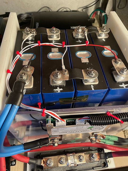
Exactly right. I actually got SS M5 screws and tapped the busbars - worked out very well. Everything is solid, everything is coated with oxgard. I used half of one single layer bus bar and put those on the main terminals, put a nylock on those leads. The other three balance leads cinched up nicely in the double-layer busbar. Thanks for this tip!
I re-crimped balance leads - I have some 22-26g crimpers in my RC toolbox. Shrink and SS screws and spring washers. All the busbars got oxgard. Removed the digital meter for the cells - the BT app is better than I had hoped so it was redundant. That simplified my top wiring by 50%.
@triplethreat at was kind enough to sell me a handful of those special little aluminum washers from McMasterCarr - they are not very big but certainly much bigger than the little post by itself. They worked perfectly! Thanks for this tip! I used 360grit paper on the terminal tops, then oxgard and the washers. Bus bars on top, then the serrated nuts. Now I wished I had used SS nylocks.
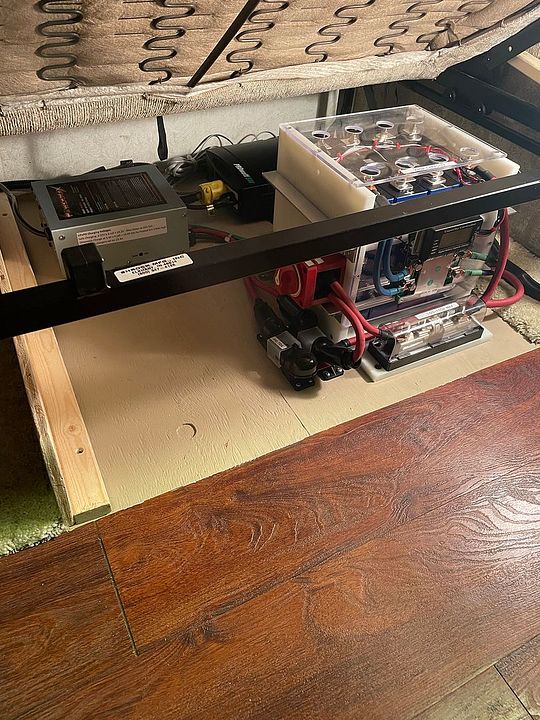
Buttoned'r up and charged to 14.2 - still a couple of runners so discharged them and the bms balanced everything at 3.55/cell.
I'm happy with the way it works and the amount of juice it will make. The chargers are all working well, and the smart shunt meter is really handy and easy to calibrate.
Test tap - used SS instead of zinc screws. These 230A bars are pretty small. 120A bms.
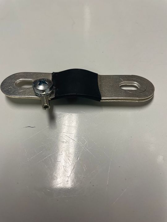
Two with washers, the rest just the post - size comparison of mating surface:
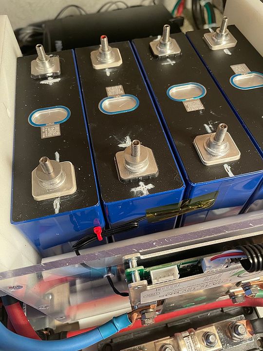
I never liked the balance lead ring terminals under the busbar nuts - this solves that.