diy solar

diy solar

Incrementally Adding AC Batteries

... Can we agree that whatever we call this is, it is a system that consists of an inverter, a DC battery, some CT clamps, some programmable logic most likely a transfer switch and other bits and pieces....

We can definitely agree on the DC battery, and other bits & pieces... ;)

Helps to always put an adjective in front of "inverter" for this discussion. AFAIK there's:
  1. grid-forming inverters (aka Off grid inverters that are voltage sources: set voltage and frequency),
  2. Grid Tied inverters (frequency matching current sources: ramp up voltage to push available watts), and
  3. grid-following inverters that try to stabilize voltage and frequency.
Like the IQ8s, the inverter in this AC battery isn't any of them, for example:
  • Shouldn't be a current source but should match frequency
  • Should stabilize voltage, but not frequency
  • Act like a voltage source, but not form a grid.
Not sure about the logic and would prefer to not have the CT if possible. Ideally I put it in my laundry room and plug the drier into it, and it into the wall. Guess that means we do need some logic, that is if there's no active grid it goes dormant.

No transfer switch like an off-grid inverter that has one built-in. But... they might need one internally to switch between being a charger and an inverter.

Wonder if I could come up with a picture of this thing... if you're trying to wrap your head around it I've probably lost a lot of others. I definitely don't want to lose the high-spirited entrepreneur who's actually going to build/sell these things.
 
Last edited:
I'm tracking.
It's a pretty cool concept to jack up the AC voltage generating a voltage that is relative to the SOC.
The theory seems sound. Detecting the frequency and synchronizing shouldn't be too hard.

I just want some of what you're drinking! ?
 
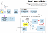
So here's a stab at it...

You'll see I broke down and used a CT on the grid feed to a transmitter. When the grid's down it transmits a low-range tone over RF. You can have multiple Magic batteries plugged in any 240V outlet (yeah, these could be 120V in any socket, but we're keeping it simple for now). They'd all be using the same transmitter. Would still like to get rid of that if someone thinks of something clever.

1593207511538.png
Logic
  • No Voltage/frequency on L1/2, no output power, also satisfies anti-islanding requirements
  • No CT Tone received (Grid Active)​
    • Charge Mode​
  • CT Tone (Grid offline)​
    • Frequency Shifted - Charge Mode: max possible charge rate set by shifted amount (but of course might be less based on SoC)​
    • Frequency not shifted - Inverter timing source synchronizes (probably use the existing AC signal as transistor's base with cap offset for perfect phase alignment)​
    • Voltage > VMax (~247VRMS) - OverVoltage protection kicks in: charges battery if they can absorb the energy fast enough or if battery full dumped to waste heat. This needs to be fairly fast, it can occur when things like inductive motors stops suddenly (e.g., air conditioning turns off, see inductive kickback spikes). It only needs to sink as much as the inverter's maximum output and probably less than a second. Heat sink is sort of a worse case scenario, big caps and clamping voltage? Also, Jack Rickard said if the voltage on a standard inverter exceeded the output voltage, the current would back-flow into battery (e.g., collector/emitter reversed)...could probably make use of that with the right transistors (might be how existing charger/inverters work). This is a swag, don't know enough about this other than it's possible as existing inverters do have this built in (e.g., Outback, Enphase, Tesla).​
    • if Surge TSink > Thot and battery > 80% disconnect until Tsink < TLow
    • If Voltage <= VMax, Inverter mode, V set to match existing V or VMin, whichever is higher. If they have the same chemistry V should naturally stay in sink equalizing SoC for all the batteries in the system. But with VMin, the AC battery is guaranteed to exhaust before the Energy Storage controller - which is important since its the one providing the frequency reference.​
    • DC Voltage <= VLowDC disconnect​
The AC Batteries "power cord" is not a "suicide plug" because it won't output any current if it doesn't detect voltage, similar to any GT inverter.
 
Last edited:
Okay, I will have some wine tonight and respond in less detail. I tried to find out more about IQ8. I did find out Enphase does their R & D in India. Good place to test how equipment behaves when the grid goes down.
 
So here's a stab at it...

You'll see I broke down and used a CT on the grid feed to a transmitter. When the grid's down it transmits a low-range tone over RF. You can have multiple Magic batteries plugged in any 240V outlet (yeah, these could be 120V in any socket, but we're keeping it simple for now). They'd all be using the same transmitter. Would still like to get rid of that if someone thinks of something clever.

Logic
  • No Voltage/frequency on L1/2, no output power, also satisfies anti-islanding requirements
  • No CT Tone received (Grid Active)​
    • Charge Mode​
  • CT Tone (Grid offline)​
    • Frequency Shifted - Charge Mode: max possible charge rate set by shifted amount (but of course might be less based on SoC)​
    • Frequency not shifted - Inverter timing source synchronizes (probably use the existing AC signal as transistor's base with cap offset for perfect phase alignment)​
    • Voltage > VMax (~247VRMS) - OverVoltage protection kicks in: charges battery if they can absorb the energy fast enough or if battery full dumped to waste heat. This needs to be fairly fast, it can occur when things like inductive motors stops suddenly (e.g., air conditioning turns off, see inductive kickback spikes). It only needs to sink as much as the inverter's maximum output and probably less than a second. Heat sink is sort of a worse case scenario, big caps and clamping voltage? Also, Jack Rickard said if the voltage on a standard inverter exceeded the output voltage, the current would back-flow into battery (e.g., collector/emitter reversed)...could probably make use of that with the right transistors (might be how existing charger/inverters work). This is a swag, don't know enough about this other than it's possible as existing inverters do have this built in (e.g., Outback, Enphase, Tesla).​
    • if Surge TSink > Thot and battery > 80% disconnect until Tsink < TLow
    • If Voltage <= VMax, Inverter mode, V set to match existing V or VMin, whichever is higher. If they have the same chemistry V should naturally stay in sink equalizing SoC for all the batteries in the system. But with VMin, the AC battery is guaranteed to exhaust before the Energy Storage controller - which is important since its the one providing the frequency reference.​
    • DC Voltage <= VLowDC disconnect​
The AC Batteries "power cord" is not a "suicide plug" because it won't output any current if it doesn't detect voltage, similar to any GT inverter.
There will likely be a little delay in the circuitry for synchronizing the phase. Matching it exactly will probably take something a little clever.

I think a small bank of super caps would do a good job of handling surges to feed it back to the system when things return to normal.
 
After a glass of wine I couldn't figure out which iteration of the design I was supposed to respond to. There was a 120v plug in version which I have seen in the market place for several years. The 240 volt version with or without using CTs.

Nevermind the latest just popped up on this thread. I will have a look at it after I have a cup or two of coffee.
 
Also, Jack Rickard said if the voltage on a standard inverter exceeded the output voltage, the current would back-flow into battery (e.g., collector/emitter reversed)...could probably make use of that with the right transistors (might be how existing charger/inverters work).
Yes, i saw that video, and that is the crux of an AC coupled hybrid inverter and how they work AFAIK. The brain even calculates the SOC of the battery and if there is not enough reserve in the battery it cranks down the GT generation to so that hybrid inverter batterys get to a SOC that gives it a reserve. That way it can buffer any swings in load or solar production that it cannot control. Increase in load and reduction in solar can be handled by battery drain. The opposite is treated with the excess energy charging the battery.That is why those systems always need the battery at less than 90% SOC. Most systems like this have a minimum battery size to GT inverter relationship. I only mention AC coupling because whether one uses frequency shift as used by AC coupling devices or some other method of modulating the GT inverter, that is the process that is fundamental to managing the inputs and outputs of such a system.
Speaking of Jack Rickard, i saw his last video and he did not sound very healthy.
 
Last edited:
You'll see I broke down and used a CT on the grid feed to a transmitter.
I think some grid sensing is built into most ATSs. The system will need more CTs than that. One would be needed on the load and one on the GT inverter AC output. Until recently the Tesla Powerwall used a Nuerio which transmitted over 485 protocol to the brain module contained in the transfer switch or the Powerwall.

Nuerio is now owned by Generac which has made some strategic moves including the purchase of a battery system manufacturer. That battery is expensive right now so they dont have a competing product to the Powerwall. However they do have a user base of devoted customers some of who may want to leverage GT solar which the cannot do with a Generac right now. If Generac were to develope an inverter based generator then they would have all the things necessary to AC couple that to a GT inverter. That would give them a system that would start within milliseconds of the grid going down, not have to use fuel until the sun went down, thereby doubling the time that a fixed volume of fuel would last.
 
There will likely be a little delay in the circuitry for synchronizing the phase. Matching it exactly will probably take something a little clever.
I don't know why that system just doesn't provide an AC source to the GT inverter and be done with it. GT inverters are designed to follow the grid. The most effective way, so far, is simple AC coupling. That is what the Tesla Powerwall uses. I have been following Elon Musk and am acquainted with several of his Engineers from SpaceX and Tesla. If there were a cost effective way to control a GT inverter without using AC coupling I think he would have done it. He does not believe in reinventing the wheel, unless he can make it better.
 
There will likely be a little delay in the circuitry for synchronizing the phase. Matching it exactly will probably take something a little clever.
GT inverters do this today and the 120V ones on Amazon don't cost much so at least we know it can be done. I suspect what they do is to use the existing signal on the transistor's base, so easy to match frequency. Obviously there's a bit of a time lag in the response, but to match phase a small capacitor in front of the base to account for the lag (which should be a fixed delay for the circuitry) should be able to offset whatever the time delay is. I bet you could have phase matching on the first cycle.

...I think a small bank of super caps would do a good job of handling surges to feed it back to the system when things return to normal.
Truthfully, I've no idea how you handle inductor kickback spikes, surges, and from over-production. GT's cap out at a max voltage, so I'm not sure how big of a deal over production is (wind turbines use load-diversion technologies, but that's a different can of worms). Straight-up inductors store energy as a magnetic field which gets dumped when the current stops (Elctroboom has an amusing video on this) and they can have big spikes. Similarly, spinning motors don't stop immediately because of their momentum. I know you could have a surge protection via clamping (video) ... but ultimately I don't know what would work best in this situation. Real EEs (e.g., @PHoganDive or @ghostwriter66) could probably tell you. I know it's done in the IQ8 and other inverters so assume it could be done here.

From @Ampster 's post above it sounds like AC Coupling solutions disconnect the renewable energy until it's battery has discharge enough that can absorb that energy fast enough. That technique wouldn't work with the magic AC battery as it doesn't have any control over the renewable energy source. It's not as bad as it sounds, by definition the renewable energy source has to be able to handle both the surges from the source and from it's own battery. The magic battery only needs to be able to absorb spikes equal to the maximum wattage it can put out, and these will probably be pretty small.

...I think some grid sensing is built into most ATSs.
All the big ones have a relay that flips so it can be used to activate auxiliary systems (e.g., a generator), even if it didn't probably easy to add a relay.
So, might not need the CT...but that's still a transmitter. Ideally it would be nice if you could just plug it in and you're done...having a transmitter/receiver just adds potential problem points. Say for example it could recognize the grid's fingerprint from the energy storage's fingerprint and just magically know or learn which was which. UPSes don't have external sensors, they just work off low voltage, so that technique might be a possibility.

...The system will need more CTs than that. One would be needed on the load and one on the GT inverter AC output. Until recently the Tesla Powerwall used a Nuerio which transmitted over 485 protocol to the brain module contained in the transfer switch or the Powerwall.
I agree the main brain needs them.

But I don't believe the magic AC battery needs more. The main energy controller in the diagram is handling the renewable energy production, the magic AC battery just matches voltage when the conditions are met -- keep in mind this isn't a current source like a GT inverter, it's a voltage source... so no current would flow unless the voltage lags.[/QUOTE]
 
Last edited:
That technique wouldn't work with the magic AC battery as it doesn't have any control over the renewable energy source. It's not as bad as it sounds, by definition the renewable energy source has to be able to handle both the surges from the source and from it's own battery.
What renewable energy source are you talking about in your diagram, that has a battery? What would a surge look like and where would it come from?
 
What renewable energy source are you talking about in your diagram, that has a battery? What would a surge look like and where would it come from?
It's any renewable energy source that has an energy storage system that can control said renewable via meets UL 1741. For example the Enphase Ensemble solution qualifies. What I don't know is if it would work in an AC Coupled solution as those systems seem to route all the power through their brain/inverter system. Need to cogitate on that.
 
Attached is a simplied schematic of a Grid Tie Battery based Inverter/Charger. Pretty much same whether Outback, Xantrex, etc. manufacturers. Rest of it is digital/firmware features by a given manufacturer to control the hardware.

If a bi-directional inverter is strange to you, it is accomplished by just slight adjustments to the MOSFET's PWM sinewave sequence duty cycling which can change power flow direction and rate of flow, on the fly, from DC to AC or AC to DC ports. The inverter can suppliment any AC port or draw from AC to charge batteries.
 

Attachments

  • Simplified GT battery inverter_charger schmatic diagram.pdf
    197.7 KB · Views: 17
This is an SMA AC coupled with a Radian using a DPST style ATS to have whole house backup rather than a critical circuit panel. See post above for AC battery logic. Hopefully obvious you could strip out the ATS and use a critical circuits panel with the same electrical impacts.

As you'll see when reading through there is a problem as Ampster previously brought up.

1593290617112.png


  • When the grid is up the dpdt ATS configuration lets the Radian back-feed the grid. (illustration above indicates grid active)
  • When the grid goes down both switches flip, the grid is disconnected.
  • The Radian's AC in/GT-out line is now dead, the AC out from the Radian's Grid forming inverter goes live. It's a voltage source, so only supplies current as needed, sets VRMS-nom = 240V and frequency to 60 Hz (U.S.).
  • The radian takes power from the solar panels and batteries; using frequency shifting and relays to control their power output.
  • The batteries are sized appropriately for the arrays so the Radian can handle surges from the renewable energy source only.
  • The load center supplies power to devices
  • The owner wanted to augment either the watts available, the watt hours available, or both so has installed 1 or more magic AC batteries.
  • In this case, the Radian only frequency shifts the renewable energy source (in the previously example it shifted all AC power)
  • If no tone from CT Transmitter (grid active), and both voltage and frequency are within range then AC Battery is in charge mode.
Grid Down Cases:
  • AC battery's CT receiver picks up the CT Transmitters tone and knows the grid is down.
  • The AC from the Radian's Grid Forming battery is always 60 Hz. This is a problem as the AC battery cannot know how much, if any, excess renewable power is available, and therefore not know if it is acceptable to charge or not.
    • As Ampster indicated earlier, it could be accomplished with a CT on the Radian's DC line (that is, no battery draw, then there's excess power). The AC battery could ramp up the charge rate util the Radian's DC CT hit some preset value (e.g., you'd still want the Radian's battery to charge too).
    • Given this discussion, it might be possible to know if there's some excess power as Vpeak would be higher while the Radian's battery is being charged.
    • Still not ideal as without knowing how much frequency shifting the AC battery can't know the maximum charge rate. Plus I hate CTs... need to find a better solution.
  • The AC battery uses the Radian's sine-wave to synchronize phase.
  • If the AC Battery detects excess power (e.g., CT, Vpeak, other magic) it enters charge mode
  • Otherwise both inverters are now acting a voltage sources, so each supplies current to prevent voltage sags from appliances.
  • If they have the same chemistry, each should maintain a similar state of charge (see this discussion)
  • The AC battery has a minimum voltage setting, so it should exhaust first near the end, important since the radian provides the frequency.
Ideally an AC battery, especially a magic one, should work in either scenario.... so this idea still needs work.
 
Last edited:
What I don't know is if it would work in an AC Coupled solution as those systems seem to route all the power through their brain/inverter system. Need to cogitate on that.
I believe the Encharge can AC couple to almost any GT system. That is an assumption that i will try to verify. Certainly, as we have discussed, it may use a propriety communication to communicate with other Enphase products which would allow it to control the other micros much faster. That would mean the GT kW to battery kWh ratio could be less.

I have four IQ7s that are AC coupled to my Skybox but have not witnessed the modulation personally. I recently installed an Envoy and added CT clamps so with the IQ 7s Enphase has a modular system that can be configured for zero export as may be required in some jurisdictions. I continue to be amazed at their adaptability and can't wait to hear first reports
 
This is an SMA AC coupled with a Radian using a DPST style ATS to have whole house backup rather than a critical circuit panel.
Essentially the whole house are critical circuits. In my neck of the woods and much of California, the meter and the main panel are integrated in such a way there is no room to intercept the feed from the meter to the main buss bar so a separate panel has to be installed.
If a bi-directional inverter is strange to you,
I think bidirectional or bimodal are terms often used to describe the modern crop of hybrid inverters. As you mention some of their ports can go in eitherbdirection.
 
so this idea still needs work.
The goals of the user need to be factored in to see if there is a market for such a device and the cost of such a device.
For example, I have plenty of inverter capacity but all I need is more battery capacity. I wanted a simple solution so it was a no brainer to buy more batteries. Now I can run my batteries at a lower SOC so there will never be any need to modulate any of my GT solar. To me that is better than having another device. Others may need more inverterv capacity and an AC battery may be just the thing they need if it is competitive with Encharge and others
 
It might be possible to "plug-in" more DC batteries to the DC side of an Encharge too to get more watt-hours.

But I suspect a lot of folks will want more of both from an Ensemble system.

During the day an Ensemble system has lots of watts as it's AC off the roof plus AC from the Encharge. But at night it's only the Encharge, which is only 1.28kW per 3 kWh battery. So, a 6kW array with 10 kWh battery gets you a max of 6+3.85=9.84 kW of inverter during the day, but only 3.84 at night. So, in my case I'll want both watts and watt hours.
 
Last edited:
Would a "standard" UL1741 compliant Grid-following inverter/charger work as the head for a "magic" AC Battery?

...

1593207511538-png.16236
Logic
  • No Voltage/frequency on L1/2, no output power, also satisfies anti-islanding requirements
  • No CT Tone received (Grid Active)​
    • Charge Mode​
  • CT Tone (Grid offline)​
    • Frequency Shifted - Charge Mode: max possible charge rate set by shifted amount (but of course might be less based on SoC)​
    • Frequency not shifted - Inverter timing source synchronizes (probably use the existing AC signal as transistor's base with cap offset for perfect phase alignment)​
    • Voltage > VMax (~247VRMS) - OverVoltage protection kicks in: charges battery if they can absorb the energy fast enough or if battery full dumped to waste heat. This needs to be fairly fast, it can occur when things like inductive motors stops suddenly (e.g., air conditioning turns off, see inductive kickback spikes). It only needs to sink as much as the inverter's maximum output and probably less than a second. Heat sink is sort of a worse case scenario, big caps and clamping voltage? Also, Jack Rickard said if the voltage on a standard inverter exceeded the output voltage, the current would back-flow into battery (e.g., collector/emitter reversed)...could probably make use of that with the right transistors (might be how existing charger/inverters work). This is a swag, don't know enough about this other than it's possible as existing inverters do have this built in (e.g., Outback, Enphase, Tesla).​
    • if Surge TSink > Thot and battery > 80% disconnect until Tsink < TLow
    • If Voltage <= VMax, Inverter mode, V set to match existing V or VMin, whichever is higher. If they have the same chemistry V should naturally stay in sink equalizing SoC for all the batteries in the system. But with VMin, the AC battery is guaranteed to exhaust before the Energy Storage controller - which is important since its the one providing the frequency reference.​
    • DC Voltage <= VLowDC disconnect​
The AC Batteries "power cord" is not a "suicide plug" because it won't output any current if it doesn't detect voltage, similar to any GT inverter.
Note: "grid-following" is a different inverter type than grid-forming (aka, off-grid inverter) or grid-tied.

If it's grid-following then:
  • it will stabilize voltage (e.g., voltage source) and frequency
  • If its UL1741 then it should know not to stabilize 61.5 to 63.17 Hz which is used to control renewable energy generation
  • Could know to recharge if frequency shifted (not available when frequency shifting isn't on the load center side of AC coupled systems)
  • Not grid forming, so if no grid is inactive (anti-islanding)
Seems to meet most the criteria with no need for CTs. Possibly missing surge/over-production protection and wouldn't know when on-grid to charge. AFAIK grid-following inverters aren't yet available for your average consumer's microgrid and not UL1741 compliant.
 
Last edited:
There is no AC battery. Any battery is DC. What you have is a system. Some systems can be combined, some can't.
 
Remember how those existing cheap GT inverters on Amazon had most everything needed to qualify for Svetz' magic AC battery with one pesky exception... that as charge sources they wouldn't hold back and drain the batteries as fast as they could once turned on?

Well, they're also made to accept a wide input of power (watts) ranges because solar panels offer a wide range of power.

So imagine a micro-controller in front of the batteries doing a PWM on the battery's output and adjusting the duty on the fly to control wattage output of the battery. Now the GT inverter is only outputting the amount of power the brain wants it to, from 0 to 100%. The microcontroller sets that based on frequency sensors and grid state.

Assuming a solar GT inverter is akin to the schematic @RCinFLA provided, then it might just be reprogramming the MCU inside, or hijacking the mosfet base via your own MCU. Use the battery side mosfets to control power input, and the output mosfets (not shown, but assuming they're somewhere) to synchronize frequency.

1597492362903.png
 
Last edited:
The moderator doesn't take well to criticism? My question is how do combined inverter generators, such as two Honda s, work. The same principal could be used to combine the DC - battery - with - inverter - system called "AC battery".
 
The moderator doesn't take well to criticism? ...
Nah, love criticism. Criticism is invaluable as it points out weaknesses/flaws; you can never have enough critics! Your post wasn't deleted for criticizing the moderator or the idea, in fact your post didn't criticize anything. It was just a repeat of post #45. Saying the same thing over in a thread without providing any additional thought/evidence/references is considered spam, it adds nothing to the conversation. That's why your post was deleted, apologies if the note explaining why it was deleted was insufficient explanation.

... the DC - battery - with - inverter - system called "AC battery".
It's not like I coined the term, don't blame me the term entered the vernacular. Even what you call a DC battery is a "system" comprised of cells. A battleborn battery for example is a series of LiFePO4 cells, temperature sensors, and a BMS. An AC battery just adds two more components, and inverter and a charger. But, by doing so removes the pains discussed in incrementally adding DC batteries (and adds a few of its own pains).

...l My question is how do combined inverter generators, such as two Honda s, work...
AFAIK, inverters and inverter gasoline generators that can synchronize the AC output use a "parallel" feature. Electrically behind the scenes a wire between them let's the inverters stay in phase.

This would be a great idea for someone building their own and not needing to interact with the grid or an existing AC battery as those devices already exist. The real question, as the op says, is how can we mix/match AC batteries from different vendors or build our own DIY version?

The grid doesn't have a "parallel" feature or a specific timing wire. But overall the concept is the same and obviously every GT inverter must match the frequency of the grid so must have a way to sense the existing frequency.

With a Tesla system you can add more Tesla AC batteries...they know how to talk to each other. Same for Enphase. Each of those companies has done the engineering and can handle the frequency shifting from CA Rule 21; but to add more battery capacity AFAIK you're locked into their product. That might not be true, any grid-tied AC battery should work together without solar. But I don't see how they can work well together without communicating with solar...someone has to be the master to set frequency curtailment and the other AC batteries need to follow.
 
Last edited:
  • Like
Reactions: Zil
Found a problem with the PWM approach.

PWM Recap
That approach used an off the shelf GT inverter as the base. Unlike a voltage source, a GT inverter is a charge source, so normally it would suck the battery dry as quick as it could dumping power whether you could use it or not (normally they convert all available power which goes into the grid acting as an infinite sink, or they shut down if the grid is off so as to not be a problem).

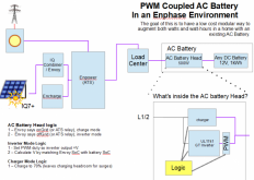
The PWM approach "fixed" that by putting a set of capacitors and power mosfets in-between the battery and GT inverter to control how quickly the battery would drain. That is the battery would look more like a constrained power source and the GT inverters output controlled. It might look something like this:

1613912115837.png
The Problem
The original thinking was that surges would travel back through a GT Inverter into the battery (Jack Rickard demonstrated this, although it might not work on all GT inverters). But, the mosfets in the PWM subsystem should be off due to a voltage spike/surge (because as the surge starts to spike the GT doesn't need to supply power and so would close them), leaving nowhere for the surge to go.

This puts us back to where we started, to expand an existing AC battery system with different technology needs something that operates as a microgrid inverter (grid following or grid supporting), that is the frequency is synchronized but it acts as voltage source. Ideally something that's UL listed and less expensive than a full blown AC Coupling solution. Right now the IQ8 fits the bill in terms of being small, but it's not available and its unclear if it'll play nicely with other technologies. Hopefully the V2H designers will implement this in their first pass solution.
 
Last edited:

diy solar

diy solar
Back
Top