diy solar

diy solar

Interfacing with Valence built in monitoring

You're talking about the hardware layer, the protocol layer is above it, in software, and doesn't really care about the signal type.

In pure theory if you connect the low side to ground and send your signal on the high side the differential input becomes single-ended. Of course doing it that way you've lost the advantages of differential signaling, so using a proper transceiver between your single ended MCU and your differential link is a good idea. But it has nothing to do with the software.
 
You're talking about the hardware layer, the protocol layer is above it, in software, and doesn't really care about the signal type.

Sure, I was just trying to design it to run on absolute minimum hardware :)
But I've come to the conclusion it's a better idea to use a proper driver for the RS485.

As you rightly say, it can be driven by any digital I/O pins from the Arduino, no need to use a hardware implemented serial port / UART.
 
Ah, that's a shame. I was looking at this inexpensive RS485 board:

It's based on the MAX13487E which looks like a good chip, but unfortunately the above board doesn't expose the Read Enable input, so it's locked in AutoDirection mode. It looks possible to hack the board to connect to this pin, but messy :(

Arduino do a more flexible board:
But it's designed to fit to their MKR boards which all need 5V, meaning extra components to run from 12V.

So still looking for a neat solution using off the shelf boards ...

I purchased and used this board with success and it's very low cost.

Richard

RS485_Board.jpg
 
Well, I'm doing an advanced one with a Nano so a basic one is totally possible ?
...
You can always bit bang any protocol on any I/Os if you don't need super high speed, it's all software. Also the serial port is used for the USB com but if you don't use the USB port in normal operation (but just for programming) you can use the serial port for whatever you want. Just be careful about the fact it'll output random stuff while you're connected by USB so it's best to unplug anything else connected to it during that time.

I'm interested to know if you actually got communication to the batteries working reliably with a Nano? I've been working on this a bit and am not convinced that it can be done reliably with software serial on a board running at 16 or 20Mhz. The baud rate needed for the batteries is quite fast (115200), and I've read a lot of people saying that the timing is inaccurate and comms unreliable when using software serial at such a rate. Having tinkered quite a bit with the inner workings of the SoftwareSerial lib (to get parity and multiple stop bit support), I'm inclined to agree.

I'm coming to the point where I'm considering a different board, maybe something like a Teensy which doesn't have the limitation that you have to use up the 1 hardware UART in order to program and debug over USB. For this kind of application, reliability is critical, no point in saving a few £/$ when caring for batteries costing 100s or 1000s.
 
I don't have Valence batteries, I'll use the 280 Ah Xuba cells, and main com will be ethernet with a chipset talking to the Nano via SPI (serial is nice for basic stuff and debugging but a PITA for everything else if you ask me...) ;)

What you can do is having two Nanos: one to act as a fifo buffer and the other one to do everything else. That way you have all the computing power available for the com only and that should be plenty enough (main clock:baud rate = about 100:1). You can also try to find a transceiver with an integrated fifo (don't know if that exists but it should IMHO...) so you can talk to it at a lower speed on the MCU side.

You can also use another MCU if you want ;)

BTW using the built-in lib isn't a good idea if you're pushing the limits a bit as the base libs often are unreliable for basic stuff (I had to rewrote half the one for LCDs and remove 90 % of the EEPROM one which is mostly uneeded bloatware... I also had to change a ugly hack they've done in the core arduino code to be able to compile properly (I'm not using their IDE...)). I mean arduino is nice because it avoids the need of an external programmer, etc... but the base code has been cobbled together and it's unreliable, slow and full of weird things.

So when you do something that should work but have a problem and you're pretty sure it isn't in your code, then copy and correct the arduino libs code you're using or just recode your own using the low-level functions... Far easier and faster than trying workarounds to make it work ;)

Understood. I'm sure the Nano is more than capable if you are using SPI comms. It's only the lack of a spare hardware UART which has me looking for alternatives. Reliable 115200 baud serial comms is an essential requirement for the Valence batteries.

I know there are other hardware workarounds: SPI to UART chips, using another MCU, etc. but this seems a more complex solution compared to just swapping to a different board/MCU. I'm also limiting my search to off the shelf boards because I don't want to make up a PCB if I can help it. This reduces the choice of interface chips I can choose from.

I think I'm going to go with a Teensy 3.2 board instead. This uses a 32 bit ARM Cortex-M4 up to 72 MHz, so quite a step up in processing power (not that it's needed), but importantly has 3 UARTS. It's still a very compact board, and inexpensive. I'm not too worried about the few extra mA it uses since it will be hanging off a 276Ah battery pack! :)

I get what you are saying about the Arduino libraries. I haven't used any other libraries in my code. I had to do quite a lot of work on the SoftwareSerial lib to get it to support parity and extra stop bits. The inner workings don't seem too inefficient but I can see cases where it may not behave itself or may interact badly with other things. But I can see that it's on the edge of being able to cope with the timing at 115200 baud. So I will be glad to ditch it and go with a different board.

The Teensy 3.2 also has a High Res Baud implementation which gives very tight timing, much better than can be achieved even with the hardware Nano UART.
 
Sounds like the Teensy is a lot more suited at your use case and will be a far better solution ;)
 
This little board looks like it would do the trick:

@t3chN0Mad what RS485 driver are you using?

That looks identical to what I am using; this is what I bought from amazon this past spring:
MAX485
 
Hi, are you kidding me?

I spent hours, days, weeks to "crack" that rs485 bus... and now you guys did it?

I have an off grid system with 20 valence batteries, I think they are from the first batch ever made. They are from before 2010. And I'm desperate to make a decent monitor system for them, I configured the system in 4 groups in series, each group has 5 batteries parallel. So this is a 48V system.

My inverter and mppt controller are DIY and it's all open source, you can find the building links on thebackshed.com. My system is a multiple kw system and reliable, I'm currently working to make it more "professional". I'm trying to get everything communicating on a rs-485 bus connected to a RPI with nodeRed to have a graphical interface.

I'm also working on my own bms and active balancers, seeing this would open some possibilities to monitor my batteries on another level.

On long term I will open those batteries to add some individual cel wires to balance on an active way, my batteries are getting old and never been treated wel so they need some strong balancing, don't know if the build in resistors are enough.

I hope to dig in the code this weekend trying to implement it in nodered somehow.
 
So, I need to sent commando's with 9600 baudrate, and I receive data with 115200?
Did you have arduino code for multiple battery id's?
Thank you in advance.
 
Hi nickskethisniksk,

There are a couple of bugs in the existing BMS.ino file so I'd recommend to wait a couple of days as some updates are coming.

Yes, essentially there are 2 different baud rates used: 9600 to wake up the batteries when they are in storage mode, and 115200 for the main communication. In both cases the Valence Module Diag software uses 8 bit, MARK parity, 1 stop bit (which is equivalent to 8 bit, no parity, 2 stop bits). However t3chN0Mad found that in practice this didn't always work and he ended up using 8E1 mode - something I've yet to verify as I'm currently waiting for the hardware to arrive.

I'll PM you some more info...

Seb
 
Regarding inter-battery balancing for series setups: in theory the batteries have the capability to do this themselves without any extra hardware, using the internal bleed-off resistor banks. But it's unlikely we will be able to crack this without analysing the communications of the actual Valence BMS hardware. Right now everything is based on analysis of the Valence Module Diag software communications, and this doesn't perform inter-battery balancing.

If you are implementing external active inter-battery balancing, then you probably don't need this internal functionality anyway.
 
Thank you for helping me.
I'm going to listen to the RS485 bus with the new parameters and try to understand the data.
I'm curious to find out, don't know if my valence bms hardware is the same as yours.

At the moment the battery "modules" are balanced with active balancers, but the inner balancers are not activated. I noticed as long as I stay between 12 and 13.9-14V per module, balancing is not that crucial (if you don't use all the potential). All cells are kept between there safety specifications that way, but that way the go out of balance. Now is the time that I need to start monitoring them better.

But if I could read all individual cells of all the battery modules it would help me to use the whole range of the batteries on a safe way. And in the winter period there are 2 months I want get everything out of this battery. The rest of the year the solarpower is more then enough.
 
I believe the older black XP batteries communicate in a similar way. Do you have the module diag software? You can install some serial monitoring software and watch the comms. I used Serial Port Monitor by Eltima.

You don't have to do anything specific to make the batteries do their internal balancing - just keep some communications going and they will stay awake. Otherwise, they go into storage mode and shut down most of their internal monitoring & balancing.
 
I did a first attempt in trying communication with the valence battery. But no luck, I loaded your code straight to the arduino Mega.
I see serial output on my scope before the RS485 ic, I use pin 2 to be able to transmit the messages. I noticed that on my arduino Mega the RX1 an TX1 are the other way around... I also have data on my A-B lines, but I got 5V signal blocks followed by 1.5V data so something is wrong in my converter circuit, I think.

It's possible the enable function is not working properly, it stays high when sniffing pin2.
I did comment out the following things because they don't make a change.

//#define hasAutoTxEnable // Comment this out if the underlying serial does not have automatic transmitterEnable
// Serial out to RS485
//#define RS485Tx 1 // 1 or 5 for Serial1, 10 or 31 for Serial2, 8 for Serial3
// Serial in from RS485
//#define RS485Rx 0 // 0 or 21 for Serial1, 9 or 26 for Serial2, 7 for Serial3

// RS485.setTX(RS485Tx);
// RS485.setRX(RS485Rx);

Tommorow is another day. :)
 
Yep another day is now!!!

So, yep forget my last message, It was late, feeling tired, sleepy eyes but I reviewed my scoop images one last time, and I didn't saw a differential signal... and the enable signal was not good. So I went a last time thrue the code and I saw the pin was not declared as output...
Wy wife will be angry not going to bed, but guess what?

So this solved the problem:
pinMode(enableRS485Tx, OUTPUT);

WOW AMAZING!! (sorry can't help it, words can't describe my feeling now!!)

Again, thank you!
 

Attachments

  • WOW AMAZING!.PNG
    WOW AMAZING!.PNG
    238.1 KB · Views: 63
Yep another day is now!!!

So, yep forget my last message, It was late, feeling tired, sleepy eyes but I reviewed my scoop images one last time, and I didn't saw a differential signal... and the enable signal was not good. So I went a last time thrue the code and I saw the pin was not declared as output...
Wy wife will be angry not going to bed, but guess what?

So this solved the problem:
pinMode(enableRS485Tx, OUTPUT);

WOW AMAZING!! (sorry can't help it, words can't describe my feeling now!!)

Again, thank you!

Yes, that's the one :)
I didn't notice this bug because the MCU (or maybe just the underlying hardware lib) that I'm using has automatic RS485 tx enable.

It should say:
Code:
    #ifdef hasAutoTxEnable
        RS485.transmitterEnable(enableRS485Tx);
    #else
        pinMode(enableRS485Tx, OUTPUT);
    #endif

I'll PM you over a newer version of my BMS code - it's evolved a bit since they other day. Now includes EEPROM event logging amongst other things. I'm planning to upload my code into the t3chN0Mad / OpenXPBMS repository on github, but still waiting for t3chN0Mad's agreement on this...
 
Thank you seb303, I've got the code running for 20 batteries on 1 bus and it's working great.
It's getting a mess to watch readings of 80 individual cells. But the balancing resistor's are at least working now.
I hope there will be enough sun to watch them getting balanced.
I'm going to have a peak in the new code now.
 
So I now monitor the batteries with an arduino MEGA, I think I will eventually design a new bms for it, the system is now protected with low/high voltage cut off, and a dump load in my 800liter water tank, controlled by an Arduino nano.
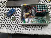
I made a small table test setup to test and debug the code, before expanding to the big system.
There was a point in life I had more then 20 batteries in service, but I ruined a few, but I have have kept the inner electronics and saved all cells I could.

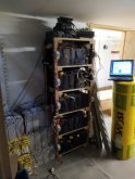
Maybe be this is somewhat of topic but I included some pictures of my system at this moment.
You will see some pictures of the GUI, this is done with an RPI 3b+ and Nodered, it acts like a server an the pages are accessible from local network with the right IP address.

I still have some work to show all the readings, but don’t know if I will keep the current layout, it’s somewhat heavy or too much in one screen.Power system.PNGValence batteries.PNGValence battery cells.PNGBattery setup.jpg
 

Attachments

  • Test setup.jpg
    Test setup.jpg
    115.5 KB · Views: 26
Last edited:
Back
Top