diy solar

diy solar

Interfacing with Valence built in monitoring

Any update on this? I checked out the github page for @skaggetse but I don't see any details about how to wire up the RaspPi to the batteries.

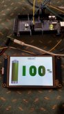
I have been low on time for this project. I am having energy-supply issues at the moment, I use my Raspberry in an EV, and need good 5v supply to power both Raspberry, Dongle and Monitor. Will have to investigate further. Right now my GUI is disrupted by kernel messages of low energy, so I can't really use this yet.

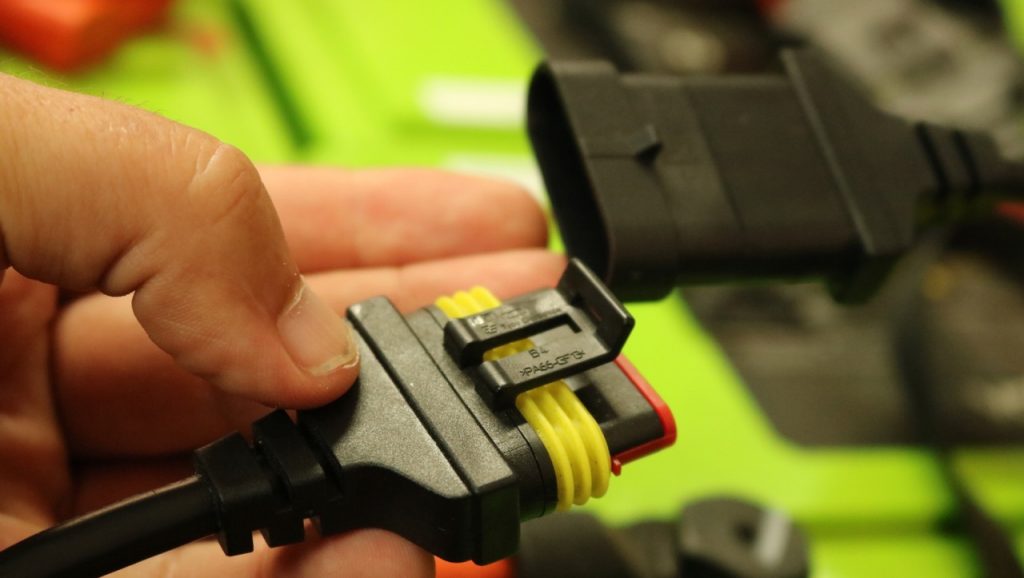
The setup is fairly easy. All you really need is a USB-RS485 dongle with FTDI chip or other Linux compilant chip or a RS485 Raspberry Pi Hat. Then you connect to the USB-RS485 dongle to the batteries. You can find how the connectors are wired up in the battery manual. Heres a blog post of Ben wiring up his batteries to the RS485 dongle;

In BMSconfig.py you set up what COM-port your USB-RS485 dongle is assigned. Then you should be good to go running the script.

Notice; This is only for monitoring at the moment. I have been able to control an external SSR via GPIO-pins, but this is experimental.
If you are using this code on other platforms than the Raspberry, you will need to uncomment all code referencing the GPIO.
 
Thanks! I think I misunderstood what the U-BMS-LV accomplished. I thought it monitored the batteries, and told the batteries to turn off under certain conditions (under-voltage, over-voltage, under-temp, over-temp). But now that I am re-looking at it, it can only support stopping charging by communicating with a device capable of the CANBus protocol. Please correct me if I am wrong on that. The only thing the U-BMS-LV does is provide the capability to monitor (which is what your project does), and to initiate battery-to-battery balancing.

I am not worried about the balancing. I am following practices to make sure the distance to each battery for load/charge is exactly the same for all batteries.

Since I don't have a CANBus capable charger (Converter), the only thing the U-BMS-LV could do is to turn off my solar which does have CANBus. So it really wouldn't solve anything. Your solution just uses a relay, so it accomplishes the same thing.

So essentially the U-BMS-LV is pointless without additional hardware.

Please correct me if I am wrong on what I am saying.
 
The U-BMS both have contactor/relay control AND CANbus control. It tells the charger over CANbus what current it wants at the moment, and but also turns the charge contactor on and off depending on the needs. It can be configured to use 4 contactors.

The problem is that it's hardcoded for a specific configuration(no of batteries etc), and it's almost impossible to reconfigure the BMS for your specific application.

I can see no mention in the documentation of an actual battery-to-battery balancing. The modules them selves balance their cells, otherwise the BMS uses a charger on/off technique to balance the batteries. When first cell reach max voltage, and the difference between the max cell and the low cell is above a certain limit, the battery rests until the highest cell voltage is below a certain value, then the charge is turned on again, and this pattern repeats until the cells are within acceptable limits.

It also balances the batteries using a "float charge", which means it tells the charger to charge at a lower voltage after the charge is complete, so that lower cells can rise a small amount.

Please correct me if I'm wrong, but this is what I've understood from reading the u-bms manual over and over.

From my experimenting, I've noticed that my XP-batteries starts to do internal cell balancing by them selves after the first cell reaches 3,4v, without any BMS plugged in, so I don't think the BMS has anything more to do with balancing than this.

I actually have an U BMS HV configured for my needs, but I wanted more specific control. That's why I devoted to this project.
Also, the Corona outbreak delayed the delivery of the CANbus adapter I needed to monitor the BMS activity.
 
If I am reading what you wrote correctly, the U-BMS has contactor/relay control, but it would still require an external SSR for that purpose. IF you have a charger capable of CANBus, then you can use that to control the charger.

For someone like me whose charger does not have CANBus, and actually I believe my PV controller doesn't have it either, I will have to use multiple relays and control those via the RasbPi? I actually have 3 chargers

1. Solar PV - 50A - Victron 100/50 has over-voltage protection, algorithms for float/bulk/charge
2. Lithium Converter (110AC > 12VDC). This actually senses voltage and turns itself on/off for float/bulk
3. Battery Combiner between AGM Chassis Battery and Lithium Battery. This has over/under voltage cutoffs

Since all 3 of these detect the voltage and turn themselves off automatically do I even need a BMS? Is the BMS just a 'feel good' at that point? If I did use a BMS, would I use 3 relays (one between each of the 3 chargers above).

The only thing I am really missing is under-voltage protection between my batteries and what is connected directly. The inverter already has under-voltage shutoff.
 
In my last post I was not referencing to the Raspberry Pi BMS, only the Valence U-BMS. It's also tricky that there are no standard CANbus protocol, different chargers have different protocols. I know the U-BMS uses the BRUSA CAN-bus protocol.

Instead of using a SSR, you should probably use a DC contactor to turn of the DC voltage from the chargers instead of the AC voltage to the chargers, and then another to control the load, or if your solar inverter have some built in switch you can trigger.
I am hacking my car, that's why I'm not controlling charge by a DC contractor, which is probably better.

How many batteries do you have? Series or parallell?

You could of course not use a BMS at all, as long as the chargers cut of at safe voltage. I would set that below the maximum om 14,6v, to not harm any cells if they end up unbalanced, especially if you have a number of batteries in series.

I have 3 batteries wired in parallel. 12V @ 414AH.

All cutoffs are at 14.4V. I have monitored my batteries for 2 months and they never go above 14.4V.

I am familiar with relays, but not DC contactors. I'll have to look into it.
 
Also, the Raspberry Pi only outputs 3v, so either you need a SSR/Contactor that accepts 3v as input, or you'll have to be creative with a separate relay to trigger the contactor/SSR
 
Thanks for your help. I ordered the RS485 and the connectors. Nothing is estimated to arrive until Apr 22nd at this point so I have some time to plan this out. I'll get my RPi up and running and then wait for parts.
 
I also will be running 3 U27-12xp's in parallel. I am unfortunately new to all things solar as well as coding so I basically have no idea what is going on but I am slowly starting to pick some things up. Someone in another thread said that the internal balancing BMS in each battery only works when connected to the monitoring software but from your experience Skaggetse the cells do balance themselves by the internal BMS? I will set the charge voltage down to 14.4 to be safe. If the cells become unbalanced how do I go around balancing them to a specific voltage. Im assuming I will also need to make sure that all three batteries remain balanced at the same voltage.
 
I am running 4 U27-12xp's in parallel charging with a VE multiplus 12/2000/80-50, VE MPPT 150/60 Tr with 4 200 watt Hightec panels, and from the alternator to protect it I'm using a Renogy DCC50S 12V 50A DC On-Board Charger with MPPT I used this DC to DC charger because of the MPPT so I could connect portable panels if I need to. I am real interested in your project and would like to contribute in any way. I'm using a VE Battery Protect for under charge on DC load and for overcharging relying on the profiles set in the VE MPPT, Multiplus and DC to DC charger but would really like a back up. I was even thinking a second Battery Protect could be controlled by my VE BMV-712 for over charge protection.
 
Hey all, first post but I've been lurking about on here and watching lots of Will's videos for a bit. I was able to find a Valance U27-XP locally and decided to try it out. I made up an RS485 cable and downloaded the software and was able to communicate with the battery. I am working on making my own BMS and thought about just getting rid of the onboard communication and hooking up directly to the temp sensors and cell voltage leads. After I got the back off and saw how nice of a job they did with everything, I was hesitant to start chopping wires. So, I started snooping on the RS485 communication and I've figured out it is using the MODBUS protocol at 9600 baud, 1 stop bit, but I couldn't get it to respond to any commands to poll the registers(command 3?) without having the diagnostic software connected. I also get parity errors on what appears to be the commands coming from the diagnostic software. If I have that running and send commands at the same time, then I can get a response. I did some more snooping and found some commands where the diagnostic software is using mark parity, so I think that could be the hang up. Does anyone have any knowledge of MODBUS and any MODBUS programming libraries that would allow me to configure a connection for mark parity?
Hello, I want to share this program with you so that you can test it and share it.
 

Attachments

  • Software Valence.pdf
    273.4 KB · Views: 63
Hello, I want to share this program with you so that you can test it and share it.


Hello,

First of all excuse me for my approximate English (thank you Google Translate ;-))

I have a system built around 4 U27-12xp batteries connected in series (48v). I charge them with a BlueSolar charger
MPPT 150-60 and 6 PV of 250w. Then a charger converter Victron Multiplus 48/1200/13.
I monitor the 4 batteries with a PC under Windows 7 and the Valence diag module software.

I will be interested in the following Valence software:

- Configuration and Monitoring
-BMS CAN monitoring
-BMS firmware update and configuration


I will be grateful if you will share them.

Regards,

Philoup
 
This is great! I'm planning to make a bkynk application to monitor the batteries data via rs485->esp8266 over WiFi. I have 8 u27-12xp in 4s2p, 14.3 kWh, same as a powerwall 2. I'll share progress with you all here and on GitHub. Thanks t3chN0Mad!
 
Hello,

First of all excuse me for my approximate English (thank you Google Translate ;-))

I have a system built around 4 U27-12xp batteries connected in series (48v). I charge them with a BlueSolar charger
MPPT 150-60 and 6 PV of 250w. Then a charger converter Victron Multiplus 48/1200/13.
I monitor the 4 batteries with a PC under Windows 7 and the Valence diag module software.

I will be interested in the following Valence software:

- Configuration and Monitoring
-BMS CAN monitoring
-BMS firmware update and configuration


I will be grateful if you will share them.

Regards,

Philoup
Hello send a message to : mongrenier@msn.com
 
Do you reckon there is a way to build a slave computer to turn on while my RV Is running, connect to the batteries via comms to turn on the internal balancing and then turn off when the RV is no longer running?

I imagine doing this would basically ensure that my batteries are always balanced since I drive my RV a lot. Basically just a slave unit that connects to the batteries while the vehicle is on.

That in conjunction with a smart charger that provides over-voltage protection (Renogy DC-DC MPPT for me) and a Victron battery protect for 12v loads and a low voltage shutoff on the inverter for 120V loads would make these things pretty much fool proof -- at least for parallel connections. Obviously would love over current/temp/etc. protection if we end up getting that far -- but for my use -- I'm mostly doing parallel connections.

I should stock up on these batteries now -- I imagine the demand is going to skyrocket for these things if a open source and easy to build BMS becomes available!

Hope you find some time to keep working on it -- I'm good with computers but the code is hard for me to follow as I have absolutely zero experience with CANBUS. Happy to help where I can -- I'll peruse the code here shortly to see if I can understand what is going on logically.

Awesome work everyone -- this is what makes the internet so great.
 
Hello,
here is a gauge which displays the battery SoC from the information given by the U BMS on its pin 2 connector B.
Enjoy.
What kind of arduino r u using? Or fit doesn’t matter? Can u please explain the 2 pins u connected? Wud u kindly share the code for the arduino with a sketch?
 
I'm starting to mess around with the python utility script that just reports batt v and temp from battery 1. I have tried to change the ID on my battery with no luck. My battery ID is 12. I've been trying to change payloadW = [0x00,0x00,0x01,0x01,0xc0,0x74,0x0d,0x0a,0x00,0x00] and payloadV = [0x01,0x03,0x00,0x45,0x00,0x09,0x94,0x19,0x0d,0x0a] to see if I can get any results, but no luck so far. Is payloadW id sensitive or is it just a general "everybody up" sort of message? For payloadV, I was thinking change the first part from 0c01to 0x0c, but I just get back "b", not a string of values. Any ideas on how to crack this? Also investigating ways to verify the script is actually talking to the com port. I see the lights flutter for a second, when I run the script, but it seems to do that no matter what com port I select, so I'm not sure that's even working.
 
Back
Top