diy solar

diy solar

Is CV charging (adsorption) even necessary?

scott harris

New Member
Joined
Jan 1, 2020
Messages
92
I am charging each of my 280 AH cells to 3.6 volts in order to do a capacity test. I use a non-programable bench charger capable of 10 amps. Setting the power supply at 3.6 volts and waiting for the current to drop off takes forever once the charger is in CV mode and the current decreases. I'm thinking of building a voltage sensing circuit which would turn the charger off once the voltage across the battery terminals reaches 3.6 volts, and then just crank the voltage on the power supply to 4.0 volts and let the cell charge at 10 amps until the voltage reaches 3.6 volts.

In other words, would be charging at 0.03C until the cell reaches 3.6 volts and then stop?

Does anyone see a problem with this method?
 
This is not something I know a ton about, some I'm interested to hear what others more knowledgeable than myself have to say. But my understanding is, with lifepo4, CV is not necessary

The reasons that you might still want it though:
1) extract maximum capacity out of your cells, or maximum capacity at a given voltage
2) allows more time for balancing if your BMS is struggling to keep your pack balanced.
 
CC/CV is what LFP likes.
Appreciate that charging LFP to 3.65 until you hit full (1%A of the entire rating, 100AH = 1A) is not giving you as much as you think. The moment you stop applying charge the LFP settles (they do that it's normal) and generally will settle between 3.55-3.50 per cell. The Amp Hours live between 3.5-3.1V which is the long flat curve that is LFP chemistries comfort zone. Charging above 3.55 is actually wasteful as you really only "may" get 5AH out of it... If you charge to 3.55 and allow the amps to fall to 1% of capacity rate, you're full. 280AH pack = 2.8A cutoff amperage.

Also, most folks allow for 10% margin at the top & bottom to maximize cell cycles & lifespan. and that's fine because they are at the useless ends on the power curve anyway. That gives you 252AH per pack usable.

DO NOT OVERVOLT LFP ! That will cause harm, result in bloating and separations if too bad.

This chart may help you to see where the "Juice" Lives.


lfp-voltage-chart-jpg.27632

SOURCE : General LiFePO4 (LFP) Voltage to SOC charts/tables 12/24/48V | DIY Solar Power Forum (diysolarforum.com)
 
I am charging each of my 280 AH cells to 3.6 volts in order to do a capacity test. I use a non-programable bench charger capable of 10 amps. Setting the power supply at 3.6 volts and waiting for the current to drop off takes forever once the charger is in CV mode and the current decreases. I'm thinking of building a voltage sensing circuit which would turn the charger off once the voltage across the battery terminals reaches 3.6 volts, and then just crank the voltage on the power supply to 4.0 volts and let the cell charge at 10 amps until the voltage reaches 3.6 volts.

In other words, would be charging at 0.03C until the cell reaches 3.6 volts and then stop?

Does anyone see a problem with this method?

What is your goal?
 
@Dzl ... bro... he said it in his first sentence. :)

@Steve_S
  1. Not sure where you get 1%. Most cell specs that specify charge termination criteria I have seen are 0.05C. This includes the Eve 280Ah cell data sheet you uploaded to Resources.
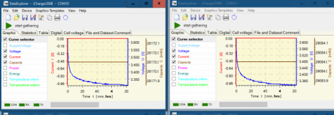
  2. I have lots of post-charge voltage logs that slow 40Ah CALB LFP cells settle well below 3.5V very quickly. Here's an example:

1606923272927.png

After 4+ hours, the cells are around 3.32V after a full charge to 3.65V with termination around .03C.
 
After experimenting with 6 different LFP packs from 12v to 48v and accurately measuring cell voltages at every stage with all types of BMSs and balancers, I can confidently recommend avoiding the final top and bottom percentages of capacity. This is where all the problems occur with cell balancing. And for what? To get another few amps out of your battery? Much better to stay in the sweet spot like on Steve_S graphs above, avoiding cell damage, and put all your saved time and money on buying extra cells. Just look on this forum for all the problems people incur trying to get every last amp out of their batteries.
 
Not sure what you mean by 'non-programmable bench supply'. As you said you set voltage I assume you mean a power supply that does not have a settable current limit.

Many bench supplies only have voltage adjust and a self protection against overload which is either a fixed current limit or an outright shut down if max current exceeded. Problem, particularly with linear power supplies (versus switching type), is the power supply may overheat if run continuously at its protection current limit.

If you are trying to get by with least expense you can get some of these buck DC to DC switchers that have voltage and current limit adjustments. They are pretty cheap in $5 to $8 range if you shop around. They have the advantage that a fixed 12v, 5 amp capable power supply or charger will produce 15 amps output at 3.6v output. If you have a 10 amp supply you can put two of these on the 12v, 10A power supply and load each DC to DC switcher with half the batteries to get 15A on each group for faster top balancing.

Always set the voltage limit of 3.65v with no load on any power supply you use. Never adjust output voltage when supply is in current limit as the voltage will not rise until load is lightened (when battery gets fully charged) causing supply voltage to rise higher then you want.

Extra current for top balancing | DIY Solar Power Forum (diysolarforum.com)
 
Last edited:
I plan on using this method for individual cell testing only. When assembled into a battery for daily use I will range between 3.0 to 3.5. But now these are new cells and I am trying to establish a baseline for capacity which I am doing between 2.5 and 3.6. Since this is only being done once, or maybe once a year, I think little harm will be done.

But the question is not really what the voltage range should be, but how to get there. My plan is to not taper power supply voltage at the knee, but to run full blast at 10 amps (still only 0.03 C) until I get to 3.6 volts across the cell and then stop. Is there any harm in that?
 
Last edited:
Always set the voltage limit of 3.65v with no load on any power supply you use.

So this is the nub of my question. When I set my power supply to 3.65v no load, it charges at 10 amps when the cell voltage is low, but slews down to just a few amps when the battery is about 75% full. What I am trying to accomplish is to charge continually at 10 amps until I reach my desired cell voltage.

I too used to set my power supply to 3.65 volts no load to make sure that the cell could never charge any higher than this amount. But if I have a cell voltage monitoring device that cuts power to the power supply when the cell reaches 3.65 (or 3.6 in my case) would not this suffice?
 
I plan on using this method for individual cell testing only. When assembled into a battery for daily use I will range between 3.0 to 3.5. But now these are new cells and I am trying to establish a baseline for capacity which I am doing between 2.5 and 3.6. Since this is only being done once, or maybe once a year, I think little harm will be done.

But the question is not really what the voltage range should be, but how to get there. My plan is to not taper power supply voltage at the knee, but to run full blast at 10 amps (still only 0.03 ) until I get to 3.6 volts across the cell and then stop. Is there any harm in that?

No, provided you don't excessively over-volt the cells. If you devise a means of cut-off, or watch it like a hawk and terminate it when the cells hit 3.6V, then you're good.
 
The above said, I would not set the PS OCV above 3.9V as a CYA measure (OCV set before connection to battery). Nor would I leave it unattended or without FREQUENT checks of cell OCV.

LFP can be charged to 4.2V, but it has massive diminishing returns and runs the risk of cell damage if done too frequently - as does holding at peak voltage for extended periods of time even under low current.

Entering into it understanding the risks and acknowledging it is completely against best practices is the first step. :)
 
If the battery AH is big enough and you have a higher amperage power supply, by all means use it. Just don't exceed max charge current for battery AH (typ 0.5 C in amps).

The higher the current during charging the longer it will take when it finally gets to 3.65v for current to taper off. You should wait until current tapers off to ensure full charge. What is a good taper off %, that depends on initial charge current. A 280 AH battery with only a couple amps of charge will be fully charged when it hits 3.65v. A 280AH battery charged at 140 amps may take a couple of hours after it hits 3.65v before current drops below 10 amps.

I would not recommend doing top balancing at extremely high current. Any slight variation in cell internal resistance will cause difference in the rate they get charged.
 
@Dzl ... bro... he said it in his first sentence. :)

@Steve_S
  1. Not sure where you get 1%. Most cell specs that specify charge termination criteria I have seen are 0.05C. This includes the Eve 280Ah cell data sheet you uploaded to Resources.
  2. I have lots of post-charge voltage logs that slow 40Ah CALB LFP cells settle well below 3.5V very quickly. Here's an example:

View attachment 29120

After 4+ hours, the cells are around 3.32V after a full charge to 3.65V with termination around .03C.
I think you got confused by my statement. The CUTOFF Amps that any charger (Solar, Inverter/charger or even benchtop adjustable should be set to cut out at 1% of the AMP HOUR RATING, for a 100AH cell that is 1 amp, 280AH that is 2.8 Amps.

This comes out of TECH / Engineering at Midnite Solar, Samlex and talks I've had with team at Rolls Surette from when they were setting up to build & sell Powerwall systems.. You can charge till the amps accepted reaches zero amps but your not getting everything you think you are. If your running Normal Production and capping at 3.55V and cutting charge once 2.8A is reach, there is no "stress" on the cell.

Some of the above discussions included properly matched, batched & binned cells which are used for commercial products with long warranty. BTW, I won't say WHO but some companies actually CAP the cells to prevent users for over/under driving them and they monitor amps received and do not allow them to reach 0AMPS FULL. Don't ask, there are NDA's involved. PS, where do you think some of my technical nuggets that I share come from ?
 
I am charging each of my 280 AH cells to 3.6 volts in order to do a capacity test. I use a non-programable bench charger capable of 10 amps. Setting the power supply at 3.6 volts and waiting for the current to drop off takes forever once the charger is in CV mode and the current decreases. I'm thinking of building a voltage sensing circuit which would turn the charger off once the voltage across the battery terminals reaches 3.6 volts, and then just crank the voltage on the power supply to 4.0 volts and let the cell charge at 10 amps until the voltage reaches 3.6 volts.

In other words, would be charging at 0.03C until the cell reaches 3.6 volts and then stop?

Does anyone see a problem with this method?
A small Canadian BMS manufacture called Electrodacus pretty much uses your above philosophy for charging Lifepo4. The designer allows solar panels to run at their native voltage and cuts the current once the highest battery in the cell pack reaches 3.55v. If you go to their web site there is some info on this as well as a blog / forum to reference. Also there are some youtube videos on this if you search the name.

MP
 
Last edited:
I think you got confused by my statement. The CUTOFF Amps that any charger (Solar, Inverter/charger or even benchtop adjustable should be set to cut out at 1% of the AMP HOUR RATING, for a 100AH cell that is 1 amp, 280AH that is 2.8 Amps.

This comes out of TECH / Engineering at Midnite Solar, Samlex and talks I've had with team at Rolls Surette from when they were setting up to build & sell Powerwall systems.. You can charge till the amps accepted reaches zero amps but your not getting everything you think you are. If your running Normal Production and capping at 3.55V and cutting charge once 2.8A is reach, there is no "stress" on the cell.

Some of the above discussions included properly matched, batched & binned cells which are used for commercial products with long warranty. BTW, I won't say WHO but some companies actually CAP the cells to prevent users for over/under driving them and they monitor amps received and do not allow them to reach 0AMPS FULL. Don't ask, there are NDA's involved. PS, where do you think some of my technical nuggets that I share come from ?

I don't think I'm confused. You say .01C based on unverifiable sources. I say .05C because that's what the cell datasheet says.
 
@Dzl ... bro... he said it in his first sentence. :)
oops....
I suppose that is about the level of attention to detail that can be expected from me at 3:43AM :rolleyes:


Then yeah, for that purpose I think CV matters. (Assuming you are trying to validate cell capacity, If all you want to do is test how much usable capacity you will have in practice, and in practice you won't be using 3 stage (or '2 stage') charging then you can probably ignore a CV taper in your capacity tests). At least that is how I see it.

If it were me, I would run 1 or 2 capacity test cycles as close to manufacturer standard test conditions as possible to verify capacity and establish a baseline. Then another capacity test using the parameters I planned to use in practice to establish a baseline actual usable capacity.
 
oops....
I suppose that is about the level of attention to detail that can be expected from me at 3:43AM :rolleyes:

Then yeah, for that purpose I think CV matters. (Assuming you are trying to validate cell capacity, If all you want to do is test how much usable capacity you will have in practice, and in practice you won't be using 3 stage (or '2 stage') charging then you can probably ignore a CV taper in your capacity tests). At least that is how I see it.

If it were me, I would run 1 or 2 capacity test cycles as close to manufacturer standard test conditions as possible to verify capacity and establish a baseline. Then another capacity test using the parameters I planned to use in practice to establish a baseline actual usable capacity.

I don't think I could have formed sentences at 3:43AM.

I think it's been stated, but CV matters more the higher the charge current is. If you're at 0.5C, heck yeah. You need a lot of it. If you're at 0.1C, you barely need it. If you're at 0.05C, you don't need it at all.
 
I don't think I could have formed sentences at 3:43AM.

I think it's been stated, but CV matters more the higher the charge current is. If you're at 0.5C, heck yeah. You need a lot of it. If you're at 0.1C, you barely need it. If you're at 0.05C, you don't need it at all.

The way I think of it (and I don't know if this is accurate or not--so disabuse me of the idea if I'm wrong), the CV phase is essentially just an increasingly slow (tapering) trickle charge. If your entire charge is a trickle (as is the case with many people buying the 5A or 10A PSU's) it is not necessary to the same extent it would be at 0.5C or 1C.

Actually now that I think of it 'trickle' might be a misleading word to use, since in practice I think it usually refers to 'trickling' current into an already topped off battery.

I imagine it like filling a bucket of water with a hose, you can very quickly get close to filling the bucket with a garden hose on full blast or a fire hose, but in order to fill it all the way to the brim without overflowing the bucket, you need to turn down the tap as it gets close to the top.
 
I imagine it like filling a bucket of water with a hose, you can very quickly get close to filling the bucket with a garden hose on full blast or a fire hose, but in order to fill it all the way to the brim without overflowing the bucket, you need to turn down the tap as it gets close to the top.
Excellent Analogy indeed !
 
Back
Top