Northernchateau
Solar Enthusiast
I personally don't use fuses unless I have to. Instead I like these as it can be reset and comes in lots of different amp ratings. get from amazon


I personally don't use fuses unless I have to. Instead I like these as it can be reset and comes in lots of different amp ratings. get from amazon
ANJOSHI Circuit Breaker 150amp 50A-300A with Manual Reset Home Solar System Fuse Holder for Car Audio and Amps Protection 12V-24V DC Reset Fuse Inverter Replace Fuses
I agree completely. I have heard the same from many other sources.And I wouldn't trust my house or vehicle with that thing unless it has UL (or equivalent) listing.
Have used breakers like that many times on other 12v application without any problems, I don't think I have ever see a UL listing on any.Amazon.com: ANJOSHI Circuit Breaker 100amp 50A-300A with Manual Reset Home Solar System Fuse Holder for Car Audio and Amps Protection 12V-24V DC Reset Fuse Inverter Replace Fuses
Buy ANJOSHI Circuit Breaker 100amp 50A-300A with Manual Reset Home Solar System Fuse Holder for Car Audio and Amps Protection 12V-24V DC Reset Fuse Inverter Replace Fuses: Circuit Breaker - Amazon.com ✓ FREE DELIVERY possible on eligible purchaseswww.amazon.com
And I wouldn't trust my house or vehicle with that thing unless it has UL (or equivalent) listing.
To receive that it would have been tested for current carrying, ability to interrupt overloads, and ability to interrupt high short-circuit current.
The following (content and grammar) do little to instill confidence:
"
Please Note:
1. Please correctly push the button to avoid damage the Circuit Breaker.
2. Please order and use the Circuit Breaker with right work temperature, to avoid it is too heat and stop work.
"
I
Have used breakers like that many times on other 12v application without any problems, I don't think I have ever see a UL listing on any.
I first saw them used in the inverter compartment on a motorhome.
 www.bluesea.com
Interrupt Capacity

| 5000A @ 12V 3000A @ 24V 1500A @ 42V |
I would agree with fuse/breaker rating sufficient for the load(s)I would select a fuse or breaker with ratings sufficient for the load and the battery's short-circuit capability. From a trustworthy source and/or with lab certifications.
A fuse/breaker is meant to protect the wire. If you have a 40A load you select a wire that can safely handle 40A. Then you select a fuse/breaker size that is between the expected max load your selected wire is going to handle and the max amps that the wire can actually handle. Since the first SCC can put out 50A, you do not want a 50A fuse or it will likely blow during normal usage. So picking a higher amp fuse is correct. Since a single, quality 6AWG wire can easily handle more than 60A, the 60A fuse is a good choice. It protects the wire while not causing nuisance trips.I would agree with fuse/breaker rating sufficient for the load(s)
In his drawing he over sizes the fuse on both solar charger by 10 amps, is that a standard practice?
Also I see he only has a 2000 watt inverter 2000/12vdc= 167 amps.
The problem I see is a 400 amp fuse with only a 300 amp switch and from the chart I look at by altE 2/0 only handles 195 amps.
IMO the weak link always needs to be the fuse/breaker but never a switch or wire.
I would agree with fuse/breaker rating sufficient for the load(s)
In his drawing he over sizes the fuse on both solar charger by 10 amps, is that a standard practice?
Also I see he only has a 2000 watt inverter 2000/12vdc= 167 amps.
The problem I see is a 400 amp fuse with only a 300 amp switch and from the chart I look at by altE 2/0 only handles 195 amps.
IMO the weak link always needs to be the fuse/breaker but never a switch or wire.
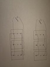
Hedges, (or anyone else) .....I need some newb clarification on your statement to "use 3 matched length cables on each positive/negative." I have attached a picture of my diagram of what I had planned for installing my 3 batteries and another diagram of what I believe you are suggesting to do. If you look at my diagram I have added a wire from battery 1 positive to battery 3 positive and then added a wire from battery 1 negative to battery 3 negative. Is this what you are saying to do? Thanks in advance!In that case redundant batteries is good. Do they have a Bluetooth app or something to check on them, so you can tell if one fails? That way, you'll know to remove it for repair, and to reduce the load you apply so remaining two won't be subject to excess current.
Two or four batteries is easy to parallel for balanced current draw. Since you have three, good to not simply parallel them with short cables but instead use 3 matched length cables on each of positive/negative. Long individual wires and short single wire after combining would help. If your inverter might draw more than what two batteries/BMS can supply, you want it evenly distributed.
Thanks for the explanation. I think I will get two 300 amp rated 4 post busbars and use exact same length wires for the battery to busbar connections and then 2 wires the same length for the busbar to inverter connections. (like the attachment). Would you recommend this strategy?No, I don't think that is perfectly matched.
Something like the the diagram on the right works for 2 batteries.
For four batteries there is a slightly more complicated scheme to accomplish similar.
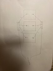
For 3 batteries, you might connect positive terminals of all three batteries to a fuse, using a 1' wire from each battery.
You might connect negative terminal to a shunt (or a busbar, or just a bolt) from all three batteries using a 1' wire from each battery.
That way, current from each battery goes though exactly 2' of wire before joining the others.
(rather than having your inverter cable go to any one of the batteries directly.)
If I was stacking three ring terminals on a bolt I think I'd place them in order A,B,C for the positive terminal and C,B,A for the negative terminal so none of the batteries sees a different path length from the others. (maybe that is splitting hairs.)

Ok, I am going to pull the newb card again..... How can I apply this to a 3 battery bank? I was planning on wiring my bank like your diagrams' "suitable for most applications" until I read a post somewhere saying that for 3 batteries you should be careful with battery cable lengths and possibly use busbars to connect in parallel. It didn't sink in until Hedges post reinforced what is probably best practice for wiring 3 batteries in parallel. I am limited in space so 3 batteries is what I have to work with in my camper. I just want to do it right the first time which is why I am asking. Thanks for the response!I cannot recall where i got this, just another possible solution.
View attachment 46889

 diysolarforum.com
I have referenced this ebook from Victron multiple times and it is helpful. I guess my question was that I was set to wire my battery bank "diagonally" like the first illustration on page 18 of the book explains (for a 4 battery bank) but I read in a post that using busbars like the 4th illustration was better. Hedges seemed to suggest using the "posts" method was acceptable and I agree. I did not understand how I could implement the "Halfway" method on a 3 battery bank, though. I just wanted to know if I should abandon my plan of wiring my 3 battery bank diagonally and use the posts or busbars method instead? Are these two methods better in some way I don't know about?You may find the following resource helpful. It includes a great discussion about connecting batteries (and many other topics).
Wiring Unlimited
Wiring Unlimited is a great resource that covers many many common topics and questions relevant to DIYers. It is a free E-book from Victron Written by Margreet Leeftink. Check it out! Download
This is what i would do for 3 batteries. If i found a balance problem later (pretty unlikely) i might give it more thought.I was planning on wiring my bank like your diagrams' "suitable for most applications"
Thanks for the explanation. I think I will get two 300 amp rated 4 post busbars and use exact same length wires for the battery to busbar connections and then 2 wires the same length for the busbar to inverter connections. (like the attachment). Would you recommend this strategy?
Thank you! I actually trust and respect member input from this forum more than the Victron handbook.This is what i would do for 3 batteries. If i found a balance problem later (pretty unlikely) i might give it more thought.