diy solar

diy solar

Is this wired correctly?

Justjeanne1

New Member
Joined
Jul 20, 2021
Messages
28
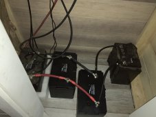
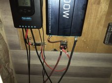
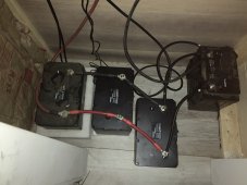
As you can see, I have a 2000w inverter, a MPPT40 charge controller, and 4 100ah lithium batteries. Currently charging in with 2 215 w solar panels. Yes I am adding more, and another charge controller BUT, not sure I need to. This is a weekend sheshed, that has 5 outlets, and a mini inverter fridge. For easy math, let’s say I am using 4 amps. Refrigerator 1.6, tv .6, and router .5, I have rounded up for ease of explanation. Not sure how much the controller and inverter are using. At 5 pm, I am 100% charged. Sun goes down (Still charging minimally) I am using 1% of my battery bank per hour. It is now 6:19pm. And I am down to 85%. How is this possible? I used a video from William Prowse for this configuration. But I must have done something wrong? Should the positive wire go from the charger to the 40amp fuse to a 200 amp breaker, where it meets with the battery Positive, or should I take that down to the battery after the 40 amp fuse?
 

Attachments

  • 34767953-338C-41CA-A7EB-D2E59C6881A5.jpeg
    34767953-338C-41CA-A7EB-D2E59C6881A5.jpeg
    179.9 KB · Views: 41
  • 9B069D9E-1B50-4DAE-A435-659D130CF1DC.jpeg
    9B069D9E-1B50-4DAE-A435-659D130CF1DC.jpeg
    253.3 KB · Views: 41
For one, your batteries are wired incorrectly and will quickly go out of balance. You should have leads for + from one end of your bank and the other leads for - from the other end of your bank.
 
For easy math, let’s say I am using 4 amps. Refrigerator 1.6, tv .6, and router .5, I have rounded up for ease of explanation.
So your "4 amps" is 4A x 24 hours = 96Ah per day.
And I am down to 85%.
How are you determining 85% ? If you are relying on the output from your Renogy Rover, I would take a look at how it is determining the SoC. Its probably assuming that 14.4V is 100% or something like that. And when the surface charge gets used and your bank is at 13.4V it is now still essentially full but the meter reads 85%.

Can you confirm any voltages and any of the SoC's? Voltage is not a prefect way to determine SoC but it may shed some light on what you are seeing.
 
So your "4 amps" is 4A x 24 hours = 96Ah per day.

How are you determining 85% ? If you are relying on the output from your Renogy Rover, I would take a look at how it is determining the SoC. Its probably assuming that 14.4V is 100% or something like that. And when the surface charge gets used and your bank is at 13.4V it is now still essentially full but the meter reads 85%.

Can you confirm any voltages and any of the SoC's? Voltage is not a prefect way to determine SoC but it may shed some light on what you are seeing.

To add to what mistersandals is saying, Voltage isnt a reliable indicator of soc for lfp because the discharge curve is so flat.
 
I Wired in parallel like Renogy told me, as these are smart batteries and supposedly will balance themselves, but I can add a lead from the first to the last. Not sure what SoC is, the volt reading is now 12.9, I think it’s at 13.4 when it’s at 100%, so you might be onto something. How can I tell how full my batteries are. I thought that was the indicator that I was looking at.
 
I Wired in parallel like Renogy told me, as these are smart batteries and supposedly will balance themselves, but I can add a lead from the first to the last. Not sure what SoC is, the volt reading is now 12.9, I think it’s at 13.4 when it’s at 100%, so you might be onto something. How can I tell how full my batteries are. I thought that was the indicator that I was looking at.
you do have them wired in parallel, but what sandals is impressing on you is that the points at which you connect your load needs to change. put the positive inverter battery cable on the positive terminal of the first battery, and put the negative lead on the negative terminal of the last battery. The SCC positive and negative should be connected the same way.
 
are you suggesting I move the negative wire from the charge controller to the last battery, the string from there up to the first? So if I cant use Renogy,s SoC to figure out how low my batteries are going down? How do I know. Based on 4 amps with no sun, theoretically I should be good for 4 days, but I need a real indicator

BTW thank you for helping me
 
are you suggesting I move the negative wire from the charge controller to the last battery,
Yes. Consider your pictured batteries, #1 on the left and #4 on the right.
Put the + from your Renogy on battery #1 and the - from your Renogy to battery #4.
Do this for your inverter too.

Its all still 4 batteries hooked together in parallel but charging and discharging evenly as opposed to mostly from battery #1.

This may or may not be your problem you are experiencing but its definitely something that will help.

Renogy customer service told me over the phone
Okay so they told you to connect them in parallel which is what we are staying with.
 
I have a 2000w inverter
Just a thought... do you experience the same battery drain with this inverter turned off? Some of these use a fair amount of energy when just turned on. And running 24/7 it can add up significantly.

Does your inverter list its stand by (idle) power usage?
 
Ok. Rewired how I think you meant. Is this correct?
 

Attachments

  • B2812407-AC78-4B50-A751-983A014B775B.jpeg
    B2812407-AC78-4B50-A751-983A014B775B.jpeg
    199.9 KB · Views: 16
I will look in my manual, but before I bought the refrigerator ( and now have added 2 additional batteries), I turned the inverter off when I left because it was drawing, but was still at 85% when I would come back in the morning, if I forgot to shut off. But I really would like to keep some drinks and my condiments in the refrigerator 24/7; so I don’t have to keep bringing that stuff back and forth., so the inverter needs to stay on for it to run.
 
Ok. Rewired how I think you meant. Is this correct?
First, stop. Don't do anything wiring or rewiring until you get confirmation from someone that what you are going to do is safe.

Here is how to achieve the wiring depicted in the picture i posted:

put the positive cable from the inverter on top of the positive cable from the scc, then put them both on the positive terminal of the first battery.

Next, put the negative cable from the inverter onto the negative cable from the scc, then put them both on the negative terminal of the last battery.

Before you actually do anything, please describe what I said in your own words so we can confirm we all understand what you are going to do.
 
Back
Top