AlanH
New Member
- Joined
- Mar 2, 2021
- Messages
- 99
Hi Guys,
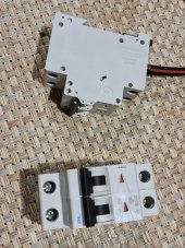
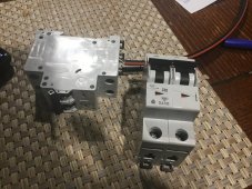
Im trying to fit a breaker between the controller and panels at the controller. Regardless which I use, the resistance is great. The controller will not recognise the voltage. If I bypass, the controller recognises the solar. Ive tried two breakers and two isolators.
Cheers guys.
Im trying to fit a breaker between the controller and panels at the controller. Regardless which I use, the resistance is great. The controller will not recognise the voltage. If I bypass, the controller recognises the solar. Ive tried two breakers and two isolators.
Cheers guys.