diy solar

diy solar

JBD 4S 200A BMS

Don’t know.. i recently tested a junctek one and so far i’m not disappointed. Looks pretty similar to a victron, but with a more fancy color display.

 
Don’t know.. i recently tested a junctek one and so far i’m not disappointed. Looks pretty similar to a victron, but with a more fancy color display.

that looks pretty nice, Looks better then mine, but at the end of the day I only really need to see how power is left. even though yours is even cheaper then what i paid.
 
Received my new 200A BMS today. Did some further testing concerning the charge/discharge/low-temp.

- Discharge only: BMS registers load fine. With temp below the charge protection, nothing happens (as expected, since i'm not charging)
- Charge only: BMS registers charge fine. With temp below the charge protection, charging stops, charge undertemp protection is displayed charging resumes when temp is above the release value
- Simultanous charge/discharge: With temp below the charge protection, charging stops, charge undertemp protection is displayed. Discharge (load) remains powered on (is NOT stopped). Only issue: App (at least on IOS) doesn't show any output amps, while it's actually discharging (powering the load)

Seems the software is like 'if undertemp is active than stop displaying any amps going in/out', while it should be like 'if undertemp is active, discharge might still work so continue to display the load current'
 
Last edited:
The postie dropped of my package of 2 x 200A BMS today, i would have preferred that it was packaged better from the sender, but i guess i'll know how they perform once i see my cells.

It does appear that i can fit some spacers under the BMS to allow mechanical fixing, i'll just have to get longer M2 threaded screws to screw it from under the bottom plate.

I grabbed the UART box along with the Bluetooth modules, so i have two options of playing around with the settings.

These JBD BMS's are are a lot bigger than the 4 year old 200a Daly BMS on my premade battery

i'm looking forwards to being able to disable charging on this BMS, a handy feature
 
Systems build complete and running for over a week of travel. Not much sun in Scotland just now but B2B doing a great job of topping up. Runs my 3kw/6kw inverter no problem for microwave and water heater and induction plate plus other 12v loads. Fiddly to mount. Need to install the heat pads ready for the cold weather.
Very pleased overall.
I'm considering one of these 200A models for my 280Ah House battery build for my motorcoach.

My inverter is a 2KW model:
2000VA @ 84% efficiency: 193A
4500VA (15 sec peak) @ 84% efficiency: 435A

In your experience, will this 200A BMS limit output strictly to 200A? Do I need to size the BMS to handle the short 435A burst capability of inverter?

Another factor is that I'd like to retain the ability of my coach to temporarily bridge the House (LiFePO4) battery to the Chassis battery (wet acid) during engine starting. I assume that depending on the charge state of the Chassis battery this could result in a full 2C drain from the House battery for a few seconds. How do I account for that in my BMS spec? Seems like I'd need a BMS that could pull the full 2C (560A) from the battery if I wanted "maximum boost". Cost is a big factor for this build so maybe a 200A BMS is enough, I'll just hold the boost button for longer to juice up the chassis battery before starting.


what kind of wiring do you have going up to your start battery. Pretty much going to guarantee your not going to see 560A through whatever wiring the motorhome put in. mine was 4 gauge. Hold the button for 30 seconds, it will recharge it. why is your chassis battery going to be stone dead in the first place?

on the inverter question, what are you going to surge here? your not going to run micro and ac at the same time, and the ac is less surge then the micro and the micro really doesn't surge over 200amp in mine which is a 1200 watt unit.

i am also looking at this for a rv

there is a surge amount, its small, not 15seconds. might be 3? not sure.
Good question/point regarding the cable size. I believe the battery to battery wiring is 2/0 AWG. This appears to be good for up to 195A or so, though I could be wrong. How does the chassis battery deliver "1000 cold cranking" amps to the starter using 2/0 AWG cable?

In any case, holding the boost button down longer should work okay as long as the chassis battery isn't stone cold dead. Why would it be dead? - sh*t happens. :) Like a month ago I left my rig at an RV place for some work and they left the key in accessory mode all night, and murdered my chassis battery.

So my rig has a convection/microwave and a residential fridge. I don't plan on running the A/C units off the inverter, but it would be nice to use the microwave without having to fire up the genny. Also plan to use a 1500w space heater from time to time.

What I don't understand is if the BMS limits the output to the rated amount (200A), or whatever value you can set in the app, or if it is capable of delivering more output for bursts, etc.?
 
Last edited:
Any info on how the Bluetooth interacts when you have two units in the same vacinity, e.g. if you have any issue controlling and how is that carried out e.g. if the same bluetooth ID is coming from both? This is regarding the 200A - H unit. Thanks!
 
What I don't understand is if the BMS limits the output to the rated amount (200A), or whatever value you can set in the app, or if it is capable of delivering more output for bursts, etc.?
FYI from some information I've uncovered it appears that the BMS does indeed support setting a max discharge rate cutoff.

Does anyone know if the BMS specs indicate support for discharging/charging over the spec (200A) for BMS in bursts?
 
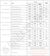
Not specific, but on the datasheet you can see some information about the protections.

The discharge overprotection current is 210A min, 230A typical and 250A max with a typical delay of 20sec. So i think it's safe to assume these are the parameters within you can configure them, thus it probably will allow 230A discharge for 20sec.

Also, the second level lists typical 440A / 320mS. So another assumption is the BMS can handle 400A for short bursts of time (<300mS).

If it would destroy the BMS before those parameters are met, that doesnt make sense.

There also is a short protection, typical 1560A @ 400uS. So this wil be another parameter to consider: The BMS will allow very short busts of even higher amps.

They even add a warning:
It is not recommended to do short-circuit protection test
LOL... like anyone is really going to test that on purpose..

1637966562689.png


At least some of this is actually kind of true, since I accidently connected a 2000W inverter without precharging. Quite sure based on the spark that was exceeding the 200A for a short moment :ROFLMAO:
 
Not specific, but on the datasheet you can see some information about the protections.

The discharge overprotection current is 210A min, 230A typical and 250A max with a typical delay of 20sec. So i think it's safe to assume these are the parameters within you can configure them, thus it probably will allow 230A discharge for 20sec.

Also, the second level lists typical 440A / 320mS. So another assumption is the BMS can handle 400A for short bursts of time (<300mS).

If it would destroy the BMS before those parameters are met, that doesnt make sense.

There also is a short protection, typical 1560A @ 400uS. So this wil be another parameter to consider: The BMS will allow very short busts of even higher amps.

They even add a warning:

LOL... like anyone is really going to test that on purpose..

View attachment 73594


At least some of this is actually kind of true, since I accidently connected a 2000W inverter without precharging. Quite sure based on the spark that was exceeding the 200A for a short moment :ROFLMAO:
This is perfect, thanks!

Looking at my wiring diagram and the inverter manual, it seems that my 2KW inverter should be fused to the house battery via 300A fuse, though I also see in the wiring diagram reference to 150A fuses in the DC distribution system, so I think this 200A BMS should be perfect.
 
I would like to get these 200A on order (is there a better supplier than China?) and it won't do me any good if the two units bluetooth radios conflict with each other in close proximity of each other (in same vehicle). I am also concerned with cooling since the Daly 250A is near as big as a shoebox and has a big fan, and these don't and are much smaller. How is this possible and can I expect a solid 200A throughput from these? I also wonder how to mount these if I abandon using the Daly in the project and use two of these instead. There is also the issue of the Daly being splash proof and thus I had planned to mount under the vehicle in a dry but open area that could receive a drop or two in a large rain storm. There's overheat as an issue as well If the battery pack is to be sealed for a heating element to keep from freezing, by mounting this BMS at the ends of the batteries in a sealed compartment, that seems like a recipe for disaster. Can anyone advise? Thanks.

*** Mounting two identical systems end to end in same long battery box and both are switchable for backup and redundancy.
I would expect that each bluetooth dongle would have it's own identifier, and you can select which one to access in the app. That seems to be the case in the recent OffGridGarage video where his app picks up another BMS nearby as well as the one on the workbench.

I can't answer your other questions. I plan to put my BMS mounted to the side of my cells in a standard plastic battery box, that is open to the air via the cable openings where the cover overhangs the sides. This will provide a small amount of air flow will protecting it from direct moisture from the top.
 
Hi, I've just ordered some cells from alibaba and looking for a bms. I'm in the UK so was thinking of ordering from China and spotted this one. JBD 4S 200A BMS Lifepo4


I'm looking for a 200amp bms as I occasionally use a microwave on my boat. I was wondering if anyone has experience of this BMS and if the low and high temperature can be adjusted and if it works.
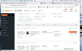
Got a 150a 48v JBD 2 days ago. Installed yesterday. LiFePO4 had been running without BMS for 5 months. Totally balanced in the first charge cycle. Like the gui as well. Extremely adjustable for just about anything you want to adjust. Easy install, too. Fired up right away with no issues. Recommended so far. Ordered thru Alibaba. Used the Off-Grid Garage video for installation help. And a 6 volt battery to start it.
 

Attachments

  • Screen Shot 2021-11-29 at 11.15.34 AM.png
    Screen Shot 2021-11-29 at 11.15.34 AM.png
    380.2 KB · Views: 21
Got a 150a 48v JBD 2 days ago. Installed yesterday. LiFePO4 had been running without BMS for 5 months. Totally balanced in the first charge cycle. Like the gui as well. Extremely adjustable for just about anything you want to adjust. Easy install, too. Fired up right away with no issues. Recommended so far. Ordered thru Alibaba. Used the Off-Grid Garage video for installation help. And a 6 volt battery to start it.

You're referring to the JK BMS. That one isn't made by JBD (JiaBaiDa) as this topic is about.

I think you're confusing JK with JBD :)
 
playing around with this 200A 4s BSM and just cant figure out it out completely.
Got the low temperature charging FET to cut off and heater pad function output to turn ON when threshold temperature is reached on the external probes. When temperature is past 'release' settings, heater pad output turns OFF and charging resumes. but I could only get this to work when I screwed with the 'calibration' settings

so, I am trying to figure out the 'calibration' settings
Situation:
- no charging current
-DSG current: set a load on the output of the BMS with a multimeter in between. Reading is 2.9A on the multimeter (2.913A)
- go to the 'calibration' tab, set 2913 in the 'DSG current' and press on the button. I get a pop-up 'calibration successful"
- go back to the "PackInfo' tab, I see current = -1.0A, same with BT dongle. Far away from the actual current draw

did the same with the 'CHG current'
just cant get this 'current meter' to work properly. is there a trick?
ok, found the answer to this problem here: https://diysolarforum.com/threads/j...scharge-currents-inaccurate.25805/post-305226
wow, plenty of wasted time on this. The instruction manual is so poorly done as well. trial and error. now I got to figure out the other stuff
 
Back
Top