


Hi all
4S 200ah lifepo4 cells (sinopoly) with JBD100A BMS.
Charged with solar (MPPT allegedly)
Im after some advice regarding the tweaking of the BMS (overkill app, but JBD BMS) settings.
I've attached:
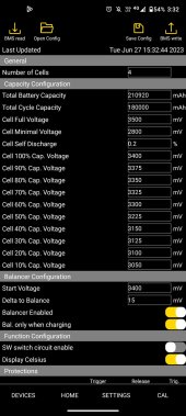
1) current settings
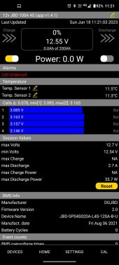
2) cell undervoltage alarm from last week (delta 0.078v)
general questions:
Q1) total battery capacity seems to have increased for some reason (i set it originally at 200,000mah)
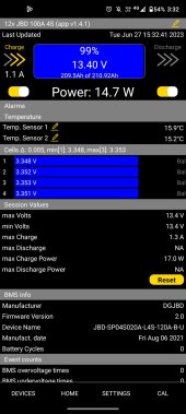
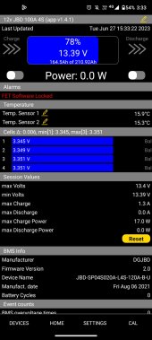
Q2) turning off discharge and charge, my voltage dropped from 13.40v to 13.39v but the capacity changed from 99% to 78%?
Q3) can the delta 0.078v be improved? I did top balance them initially.
I think my main issue is that ive set the config settings wrong (possibly too conservatively).
My main priority is cell longevity.
Thanks
4S 200ah lifepo4 cells (sinopoly) with JBD100A BMS.
Charged with solar (MPPT allegedly)
Im after some advice regarding the tweaking of the BMS (overkill app, but JBD BMS) settings.
I've attached:
1) current settings
2) cell undervoltage alarm from last week (delta 0.078v)
general questions:
Q1) total battery capacity seems to have increased for some reason (i set it originally at 200,000mah)
Q2) turning off discharge and charge, my voltage dropped from 13.40v to 13.39v but the capacity changed from 99% to 78%?
Q3) can the delta 0.078v be improved? I did top balance them initially.
I think my main issue is that ive set the config settings wrong (possibly too conservatively).
My main priority is cell longevity.
Thanks
Attachments
-
 WhatsApp Image 2023-06-27 at 10.00.42 PM (3).jpeg49.2 KB · Views: 96
 -
 WhatsApp Image 2023-06-27 at 10.00.42 PM (1).jpeg49.3 KB · Views: 76
 -
 WhatsApp Image 2023-06-27 at 10.01.48 PM.jpeg47.1 KB · Views: 79
 -
 WhatsApp Image 2023-06-27 at 10.00.42 PM (2).jpeg56.8 KB · Views: 92
 -
 WhatsApp Image 2023-06-27 at 10.01.01 PM.jpeg60.4 KB · Views: 99
 ) is 78%.