


unseengundam
New Member
- Joined
- Nov 27, 2021
- Messages
- 21
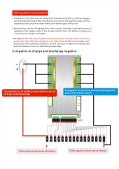
I have a JBD-AP21S001(150A) BMS that seems to require a wried short circuit for a 16S config. This one has B0 to B21 wires; see below.
The last six wires are shorted together on the 2nd to the last cell. I tried a few configurations of shorting, but the BT app still shows at least 17 cells. I am sure I am confused about which wire shorts are together; the manual and the seller are confusing to understand.
Does the wire color such as red, black, and white mean anything? Or are they all treated the same? I might need short the Black & white wires together on 2nd set of wires. Any suggestion on the right configuration.
Thanks
")