diy solar

diy solar

Dead short fuse trip experiment using an MRBF fuse

How about we make some kind of fundraise and hire a professional to test all these fuses, maybe even find equally effective alternatives? Which profession works with this sort of thing?

Or, we keep buying whatever is in trend, MRBFs, T-class, and whatever fuse they throw at us and hope it works when shtf. :)

It's a bit strange that there's not a least one guy who works with this stuff in the DIY community who would shed light on these things once and for all time. At least I haven't read about one so far.
 
Nice stuff. I requested T class testing a month or so ago and pretty much everyone just complained saying there's no reason to test lmao.
Gonna request they get tested too. I'll buy you a https://www.amazon.com/gp/product/B0BQZ8715R/ if you want because I don't think bluesea (little fuse) should be the only fuse anyone trusts.

Do you have a way to limit amperage to test like a 150amp fuse when it blows at.. say 200-250 amps etc?

How about we make some kind of fundraise and hire a professional to test all these fuses, maybe even find equally effective alternatives? Which profession works with this sort of thing?

Or, we keep buying whatever is in trend, MRBFs, T-class, and whatever fuse they throw at us and hope it works when shtf.

It's a bit strange that there's not a least one guy who works with this stuff in the DIY community who would shed light on these things once and for all time. At least I haven't read about one so far.
yep I'd like all of them tested. I don't think datasheets and curves are always accurate as they are not accurate for microchips, processors, micro controllers, mosfets, transistors, etc that I have used for decades.
Thus I don't believe these fuses, regardless of company, are going to also 100% always be 100% accurate.
 
Found a very interesting discrepancy. Ten year old packaging shows “32V DC Max”
Latest website site shows Maximum 58V DC.
I’m wondering how catastrophic the result would be at 24 and 12 volts with the higher current rated fuses. At 48 volts and higher current, there’s obviously a heck of a lot of energy/plasma/molten metal wanting to exit. I’m pretty confident that a T class fuse + quality holder won’t be squirting sparks.
Again, thanks to Johan for this test. Previously, I thought that MRBF’s were great if you weren’t concerned about “fast blow”.

Blue Seas put out some information a few years back that their 48 volt rating was a maximum, not an indication that it was for a 48 volt system. I think they recognized that 48 volt systems were being implemented more and more. The newer 58 volt rating likely included a change to their products to handle that voltage.
 
I’m pretty confident that a T class fuse + quality holder won’t be squirting sparks.
Again, thanks to Johan for this test. Previously, I thought that MRBF’s were great if you weren’t concerned about “fast blow”.
In my opinion the whole fast-blow "idea" of class-T is bit ill-informed.
Any decent inverter should have very fast overcurrent limiting built-in. Only if something goes terribly wrong in the inverter it will draw enough current to blow fuse. Fast fuses are typically too slow for protecting the transistors and inverter itself has so much input capacitance that if something goes wonky with the switching stage it will easily self-destruct irregardless of fuse selection. Fusing is only to serve as a fire protection.
 
Nice stuff. I requested T class testing a month or so ago and pretty much everyone just complained saying there's no reason to test lmao.
Gonna request they get tested too. I'll buy you a https://www.amazon.com/gp/product/B0BQZ8715R/ if you want because I don't think bluesea (little fuse) should be the only fuse anyone trusts.

Do you have a way to limit amperage to test like a 150amp fuse when it blows at.. say 200-250 amps etc?


yep I'd like all of them tested. I don't think datasheets and curves are always accurate as they are not accurate for microchips, processors, micro controllers, mosfets, transistors, etc that I have used for decades.
Thus I don't believe these fuses, regardless of company, are going to also 100% always be 100% accurate.
I used some South Bend fuses simply because BUSS wasn’t available or some scalpers were flipping them for ridiculous prices during pandemic. So yeah I’d love to see if those spit lava when spanked.
 
In my opinion the whole fast-blow "idea" of class-T is bit ill-informed.
Any decent inverter should have very fast overcurrent limiting built-in. Only if something goes terribly wrong in the inverter it will draw enough current to blow fuse. Fast fuses are typically too slow for protecting the transistors and inverter itself has so much input capacitance that if something goes wonky with the switching stage it will easily self-destruct irregardless of fuse selection. Fusing is only to serve as a fire protection.
Some bms’s have very fast over current protection as well. Now I’m just liking the T class for perhaps better containment of the boom. A good test might just be the last word thou.
 
Some bms’s have very fast over current protection as well. Now I’m just liking the T class for perhaps better containment of the boom. A good test might just be the last word thou.
I would never count on the BMS alone being able to survive short-circuit on the output. Disconnecting on overload is fairly easy but controlled disconnect during short-circuit on 48V system is not a trivial task as the current will rise to thousands of amps in less than 100 microseconds.

Saving the BMS could be actually one benefit of current-limiting fast acting class T or similar fuse. BMS typically has very hefty mosfet array that can handle thousands of amps in the on-state for a short perioid of time as long as fuse breaks the circuit. So the bms might survive fast-blow fuse but fail with slow-blow.
 
Last edited:
I used some South Bend fuses simply because BUSS wasn’t available or some scalpers were flipping them for ridiculous prices during pandemic. So yeah I’d love to see if those spit lava when spanked.
Yea and I remember your several threads.. and I had threads on it too. I still use them. I have 125amp fuses and 125amp breakers on wire that can handle 200 amps. The breaker will trigger first and unless it's a dead short, the fuse probably won't ever trigger since breaker will first.
but they're way less money than bluesea so I don't think bluesea is worth it. I assume they work..
....but if testing shows they blow at like 200000 amps instead of 125 then I'd probably switch too LOL

oh yea I also have the JK bms with the over current protection so I guess all my batteries have 3 levels of protection
 
As it sounds like you're planning on repeating this test; a few suggestions for protection.

1. Have a loop of the wire away from the rest that you'd cut with the branch cutter
2. Swap the branch cutter to an insulated heavy gauge wire cutter
3. That loop should also have a bus bar so you can unbolt should cutting the wire not suffice to end the current flow.
4. A blade style disconnect? I think they make those for high current DC
 
Yea and I remember your several threads.. and I had threads on it too. I still use them. I have 125amp fuses and 125amp breakers on wire that can handle 200 amps. The breaker will trigger first and unless it's a dead short, the fuse probably won't ever trigger since breaker will first.
but they're way less money than bluesea so I don't think bluesea is worth it. I assume they work..
....but if testing shows they blow at like 200000 amps instead of 125 then I'd probably switch too LOL

oh yea I also have the JK bms with the over current protection so I guess all my batteries have 3 levels of protection
So to protect my system, I’ve got the inverter’s default over current, high voltage disconnect (thermal /magnetic breaker), Fast blow T class fuses at each BMS rated well below the cable and BMS ratings, the over current protection set well below the peak rating of each BMS. Not too much else can be done reasonably, however I figure that a massive, instantaneous short could still kill the system, but it won’t hopefully catch fire.
 
Every over current protection device requires some time before it can shut off the current flow. An instant dead short can hit several thousand amps long before a 100 amp fuse or breaker can open. And a Mosfet based BMS is not going to save you. In fact, many Mosfet failures result in them being a dead short as well. So the BMS can lock on in a bad over current failure.

A worst case might even be the Mosfet H bridge in the inverter going dead short. So the inverter is not saving you. Then the BMS Mosfets also fail shorted, no help there. The fuse strikes a plasma arc, because you used a 12 volt Mega Fuse. The breaker welds shut because it was only rated for AC. Oops.

Protecting a high current DC system is not trivial. I have a 100 amp CNL fuse (125 volt rated) on each of my 4 battery strings, and then a Class T 225 amp fuse on the main run from the battery bank to the inverter. And I will soon, also have a 125 amp 400 volt DC rated breaker on each pair of battery strings.

While I hope to never have anything fail, I think I covered my bases if something bad does happen.

I use a 200 amp 400 volt DC breaker, thou I don’t think it’ll be the first thing to ever trip, but it at least won’t have a destructive arc show within when it gets used.
 
Every over current protection device requires some time before it can shut off the current flow. An instant dead short can hit several thousand amps long before a 100 amp fuse or breaker can open. And a Mosfet based BMS is not going to save you. In fact, many Mosfet failures result in them being a dead short as well. So the BMS can lock on in a bad over current failure.

A worst case might even be the Mosfet H bridge in the inverter going dead short. So the inverter is not saving you. Then the BMS Mosfets also fail shorted, no help there. The fuse strikes a plasma arc, because you used a 12 volt Mega Fuse. The breaker welds shut because it was only rated for AC. Oops.

Protecting a high current DC system is not trivial. I have a 100 amp CNL fuse (125 volt rated) on each of my 4 battery strings, and then a Class T 225 amp fuse on the main run from the battery bank to the inverter. And I will soon, also have a 125 amp 400 volt DC rated breaker on each pair of battery strings.

While I hope to never have anything fail, I think I covered my bases if something bad does happen.
Yea I've tried to explain that to people before. People think without a fuse, without a breaker, the short protection of a BMS will save them...
Somehow software is going to save them from that type of failure? hahahahah
A BMS can save most of your stuff though, by dying before everything else does, which is what I'd expect. At least it's only a $80-$200 failure

I haven't seen anyone really thinking that here though, it's more random people on youtube / reddit that I've seen absolutely swear by the bms short circuit protection being enough
 
was replacing the bms in an SOK 280, and it looks like a class T could be added inside to the connection to the terminal (maybe height problem). Internal fusing would simplify connections if appropriate.
 
Introduction
Marine Rated Battery Fuses (MRBFs) are sometimes used to replace Class T fuses due to supply chain issues, ease of installation, space constraints, and cost. However, the breaking capacity of MRBF fuses is significanly lower than that of Class T fuses as shown in Figure 1.

View attachment 202479
Figure 1. Ampere Interrupting Capacity vs DC Voltage Rating

Problem
How will an MRBF fuse behave when subjected to a dead short outside of the fuse specifications?

Background
If the fuse does not quench the arc, then hot plasma could theoretically turn the fuse into a near-perfect conductor and cause a fire, instead of a near-perfect isolator that prevents fire.

In a previous experiment, an MRBF fuse was blown using an LFP battery, and a relatively small diameter wire was used, resulting in a relatively large circuit resistance, so it may not be a conservative representation of many battery installations.

Goal
The goal is to create a practical, realistic, and relatively safe near-worst-case dead short experimental setup using a relatively large capacity (Ah) battery together with large-diameter and short-length conductors that can be used to observe how MRBF fuses behave when a dead short occurs.

Experimental setup
See Figure 2 for the experimental setup.

View attachment 202470
Figure 2. Experimental setup.

Parts used:
  • MRBF fuse block and MRBF fuse rated 150A (random rating choice).
  • Battery: 4 x brand new Victron Smart Lithium 330Ah 12V LFP in series, 48Vnom; never charged or discharged; NO internal BMS; Battery voltage = 52.7V = 3.29Vpc (SoC unknown).
  • Battery interconnects ("busbars"/ battery cables): 4/0 AWG UL-listed pure copper. Total cable length ~20" (500mm).
  • Tinned copper lugs, hammer crimped on solid concrete substrate (one sample cut in half after crimping to verify quality which was good). Lugs degreased before mounting, torqued to spec.
  • Dead short initiation device: 250A snowmobile winch relay (solenoid, approx 5Ω), triggered remotely with power supply set at 14Vdc.
Some of the safety aspects for this experiment:
  • Backup circuit breaking methods in the order of prioritized use:
    1. Use extension pole tree branch cutter. This cutter was verified to cut like a knife through butter through copper cables. Once cut, the weight of the relay (black box with black tape in Figure 2) will pull down one cut end to create a gap large enough to quench the arc. Locally remove cable insulation to reduce cutting resistance.
    2. In case method (1) fails: Use a stand-by impact drill set to CCW rotation with socket wrench attached to disconnect interconnect bolt.
    3. In case methods (1) and (2) fail: Use manual cable cutter.
  • Safety goggles; gloves; fire protective clothing.
  • Fire extinguisher nearby especially for extinguishing burning insulation after breaking circuit.
  • Second person with phone to call for help.
Theory
The initial calculated (estimated) theoretical dead short current is approx 14,000A (14kA). This is wel outside the MRBF specs as shown in Figure 1. The instantaneous theoretical dead short power is in the order of 700,000W (700kW), which roughly matches the maximum power of a Tesla Model S Plaid 😨. Should we really do this? Just kidding - Curiosity wins :p.

Results
  • The fuse successfully quenched the arc in the order of one video frame rate interval, in this case 30fps, so 1/30 = 0.033s. See also Figures 3 and 4.
  • The fuse polycarbonate (assumption; probably not acrylic) housing back wall blew out and landed ~10 ft away. See also Figure 5.
  • Sparks of molten copper blew out and landed 1-3ft away.
  • The relay welded closed (this was expected) and had to be taken apart to break the contact points loose as shown in Figure 6.
View attachment 202467
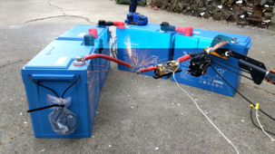
Figure 3. This is what the fuse blowing looks like in close-up (most dramatic video frame).

View attachment 202489
Figure 4. Fuse blowing process.

View attachment 202484
Figure 5. The MRBF fuse after blowing. The separation occurred at the plastic weld / glue seam.

View attachment 202493
Figure 6 - Welded relay. Only the right two studs were used.

Conclusions
When operating outside of the MRBF specs, conservatively expect at least the housing to fail and molten copper and plastic debris to fly around. This experiment is anecdotal only and needs to be repeated many times to show repeatability.

Recommendations
  • Repeat this experiment to evaluate repeatability.
  • Vary the fuse current rating: A 300A MRBF fuse could yield different results.
  • vary the battery SoC.
  • Etc.
Ideas and criticism, preferably constructive with references when making claims, are welcome.
Very informative subject matter. Safety is my concern with any system or device. If a thermal event does occur, these are the gases released. Just a FYI for the forum. LFP is safer and I assume it predominates chemistry in most stored energy. However with the pouch style and lithium-ion chemistry, dramatic and fast-moving incidents occur. No news to most here.
 

Attachments

  • IMG_0279.jpeg
    IMG_0279.jpeg
    153.7 KB · Views: 14
Mounting NH fuses is even worse.
How do you work that out? I have class T on one of mine. It's the larger fuse as I am fused at 225A. The NH fuse holder is shorter and more compact. I have one of these mounted on my other battery. Much prefer the NH fuse
 
How do you work that out? I have class T on one of mine. It's the larger fuse as I am fused at 225A. The NH fuse holder is shorter and more compact. I have one of these mounted on my other battery. Much prefer the NH fuse
I guess it depends on what hardware you use but for example Blue Sea holder is 178mm in total lenght

And NH1 fuse holder is 250mm long: o_O

More extreme example: something like http://www.vte-europe.com/content/electromech/fuse/html/classt/classt.php
Up to 400A and only 45mm between centers on lug studs, whereas 400A rated NH2 fuse holder is 175mm between lug studs.
 
Yea I've tried to explain that to people before. People think without a fuse, without a breaker, the short protection of a BMS will save them...
Somehow software is going to save them from that type of failure? hahahahah
A BMS can save most of your stuff though, by dying before everything else does, which is what I'd expect. At least it's only a $80-$200 failure

I haven't seen anyone really thinking that here though, it's more random people on youtube / reddit that I've seen absolutely swear by the bms short circuit protection being enough
To a certain extent I believe the BMS will work. The inadequate (underrated) MEGA fuse is the secondary stop.

Maybe a brave soul with a surplus BMS could do a test also....

Real test would be several in series and see what goes first :cool:
 
I guess it depends on what hardware you use but for example Blue Sea holder is 178mm in total lenght

And NH1 fuse holder is 250mm long: o_O

More extreme example: something like http://www.vte-europe.com/content/electromech/fuse/html/classt/classt.php
Up to 400A and only 45mm between centers on lug studs, whereas 400A rated NH2 fuse holder is 175mm between lug studs.
My NH00 fuse holder is 135mm long. 160A fuse. Like class T, the fuses and holders get bigger depending on the rating of the fuse.
Since I fuse each battery and I run a 24v system 160A for each battery is plenty for me. My largest load will come via the 3kw inverter which limits me to about 125A. I can charge at up to 115A so well within the 160A fuse rating. My NH00 fuses and holders are a fraction of the cost of class T. Even if they were twice the size, I have plenty of room
 
To a certain extent I believe the BMS will work. The inadequate (underrated) MEGA fuse is the secondary stop.

Maybe a brave soul with a surplus BMS could do a test also....

Real test would be several in series and see what goes first :cool:
I've seen the BMS work several times via other people. They end up with a hole through them where they melted.
 
Thanks everybody a lot for the input. Feature requests so far:
  • Create current versus time plot, e.g. using an oscilloscope / clamp meter with inrush (the latter has too low max current).
  • Test more fuse types: Class T (example); bs88; NH; 300A MEGA; CNL; South Bend.
  • Test breakers - cheap amazon etc. Install in wrong polarity too.
  • Test 3D printed shields.
  • Add BMS to circuit, e.g. with serverrack form factor battery, optionally in series with overcurrent device(s).
  • Add inductor coil in circuit as soft start. How to best do this?
  • Test 12V and 24V in addition of 48V.
  • Fundraise and outsource to pros.
  • Apply controlled constant current. Generate DC time-current "trip-curves" for a set of given constant currents.
  • Add wire loop away from rest to cut, cut with better cutter, have disconnect bolt and blade style disconnect
Requesters: @MattiFin @time2roll @HRTKD @740GLE @OzSolar @GXMnow @douglasheld @G8trwood @Hedges @Pi Curio @gotbeans @Skypower @Sennen

Update based on requests - let's start with the first one

Goal
: Create a measurement setup for measuring the current versus time, including the maximum short circuit current and the fuse clearing time.
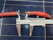
Test "fuse": 22 AWG | copper | 25mm length, see Figure 1.
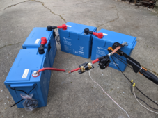
Experimental setup: Roughly the same as previously, but now expanded with data acquisition: Victron 500A SmartShunt (only using shunt part, not using the Victron measurement circuitry) → Arduino UNO → USB → laptop → Putty → *.txt → Excel. see Figure 2.
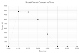
Result: The maximum current seems to be roughly 8kA* and the "fuse" clears in roughly half a millisecond as shown in Figure 4. The maximum sampling rate I could squeeze out of the Arduino so far is roughly 7 kHz. To see what happens within the first 0.138ms, faster hardware is required. Also there seemed to be random noise equivalent to 120A. The contactor did not weld closed this time (the same contacts were used as before, filed down a bit after breaking loose).
Conclusion: For data acquisition, the arduino works, but the sampling interval is close to the fuse clearing time. For a higher sampling rate, a better solution like an oscilloscope is probably preferred over the Arduino.

*Measurement accuracy estimation (for currents exceeding 7kA): Roughly 1%, based on Arduino's ATMEGA328P 10bit ADC specs of 2 LSB error . This assumes ADC reference voltage calibration, which was done just before (not during) the experiment.

smallPXL_20240322_232957765.png
Figure 1: Test "fuse".

smallPXL_20240323_000905005.png
Figure 2: Test setup.

smallvlcsnap-2024-03-22-21h25m30s431.png
Figure 3: Fuse blows.

plot.PNG
Figure 4: Short circuit current vs time.
 
Last edited:
  • Test more fuse types: Class T (example); bs88; NH; 300A MEGA; CNL; South Bend.
Would add one more - gPV 10x38 DC 32A Fuse with Din rail 32A fuse holder


  • Fundraise and outsource to pros.
The post I made was more of a call to the group for action and in no way a reference to your outstanding work and dedication. Just to clear that out.

We spend hundreds on DC protection, without much, if any empirical data. Far cheaper for each to chip in something and have a real-world test done on the most popular DC protection in our systems.


Personally, I prefer seeing this done by talented individuals like you. You seem to understand most of the things involved in these tests.

For simple people like me, all I care about and mostly can comprehend is if the fuse can repeatedly open the circuit in a dead short, what amperage it managed to interrupt at what voltage and how fast was it(approximate Short circuit current vs time for reference).

Not to take any more of your time with my lengthy post, keep it short, and get down to business as they say;

Currently, I have an interest in 10x38 gPV fuse and din rail fuse holder.

If you would be interested in testing a DC gPV 10x38 32A fuse in a 32A 10x38 Fuse holder on a 48V battery, preferably 2 times, I would like to first sponsor the following parts for the test - Fuse and Fuse Holder, and then, in addition, a token of appreciation for your effort to your PayPal post-test result publication in here for everyone to see.

Thank you for sharing your work and enthusiasm with us. This type of content is well overdue and is invaluable to the DIY solar community.
 
So, lemme get this straight, the fuse was given a massive over current and it blew with some firey results. It prevented an arc from forming. Pretty much what it was designed to do and if this was connected to wires and equipment it would have prevented the wires from melting. I can't recall how many times I have read here "fuses are to protect wires, not equipment", but it is a bunch.

A bit of molten metal flying strikes me as about as dangerous as when you flick solder off the tip of the iron. If you look at the fuse element through the plastic there isn't much metal there. Also I am pretty sure the fuse element is tin mixed with something. Would I want it on my bare skin? No!!! Do I think it would start a fire unless it did as someone mentioned and sparked the vent from a battery? Not likely.

I would would like to see other fuses tested with this method to see how they react.

Seems like it would be possible to build a test rig that is able to have a variable current output and increase across the rated current of the fuse. I am not that sort of engineer.
 
can't recall how many times I have read here "fuses are to protect wires, not equipment", but it is a bunch.

A bit of molten metal flying strikes me as about as dangerous as when you flick solder off the tip of the iron
heavily agree with both. Fuses are used all over electronics to protect electronics, not just wire.

Also yea maybe just try not to lay some dry hay & straw on your batteries and they won't catch fire with this :^)
my boxes are already concrete & metal though, pretty overboard and t class.. so probably even less of a reaction but we'll see. Definitely would like variable current output but dead short is good place to start
 
Today two more 22 AWG copper fuse wires were blown, similar to the previous black curve. The 22AWG copper wire fusing current is approx 41Adc (Preece), so this is a relatively small fuse having a clearing (blowing) time that is at the lower end of what I expect to be used in practise.

Goal: Evaluate if more data can be squeezed out of the little Arduino.
Result: Three times more data 😀, resulting in >10 samples per (in this case relatively small duration) dead short events, see also the plot below. The sampling interval improved from 138 down to 45 microseconds. This went at the cost of resolution: The smallest measurable current increment is no longer 32A, but now approx 80A, which could be acceptable because the currents of interest are two orders bigger, i.e. 8000A. Note in the plot:
  • Orange curve: Again a ~25mm fuse wire length (just like the black curve from the previous experiment repeated here), but one battery terminal bolt was left loose at zero torque 🤨. Still got the full 8kA current :unsure:, yet zero damage at the loose stainless-bolt/lug/terminal :unsure:.
  • Green curve: ~10mm fuse wire length (less than half the previous two), Torqued everything to spec again, reducing the circuit resistance.
Conclusion: Not sure if I should purchase an oscilloscope (Siglent SDS1202X-E or so) bc I would not use 95% of its features BUT it could be a nice data acquisition tool to doublecheck the Arduino and can be used for other things in future etc.

Capture.PNG

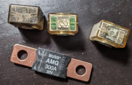
Next up: MRBF 30A, MRBF 300A, MEGA 300A. The 150A MRBF at the far left was the first one blown.
For special requests, we can talk using private messaging on this forum.

1711341866791.png
 

diy solar

diy solar
Back
Top