Johan
Off-grid energy systems enthusiast.
Introduction
Marine Rated Battery Fuses (MRBFs) are sometimes used to replace Class T fuses due to supply chain issues, ease of installation, space constraints, and cost. However, the breaking capacity of MRBF fuses is significanly lower than that of Class T fuses as shown in Figure 1.
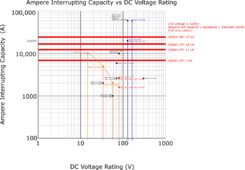
Figure 1. Ampere Interrupting Capacity vs DC Voltage Rating
Problem
How will an MRBF fuse behave when subjected to a dead short outside of the fuse specifications?
Background
If the fuse does not quench the arc, then hot plasma could theoretically turn the fuse into a near-perfect conductor and cause a fire, instead of a near-perfect isolator that prevents fire.
In a previous experiment, an MRBF fuse was blown using an LFP battery, and a relatively small diameter wire was used, resulting in a relatively large circuit resistance, so it may not be a conservative representation of many battery installations.
Goal
The goal is to create a practical, realistic, and relatively safe near-worst-case dead short experimental setup using a relatively large capacity (Ah) battery together with large-diameter and short-length conductors that can be used to observe how MRBF fuses behave when a dead short occurs.
Experimental setup
See Figure 2 for the experimental setup.
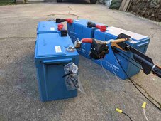
Figure 2. Experimental setup.
Parts used:
The initial calculated (estimated) theoretical dead short current is approx 14,000A (14kA). This is wel outside the MRBF specs as shown in Figure 1. The instantaneous theoretical dead short power is in the order of 700,000W (700kW), which roughly matches the maximum power of a Tesla Model S Plaid . Should we really do this? Just kidding - Curiosity wins
  .
.
Results
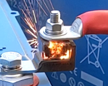
Figure 3. This is what the fuse blowing looks like in close-up (most dramatic video frame).

Figure 4. Fuse blowing process.
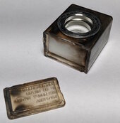
Figure 5. The MRBF fuse after blowing. The separation occurred at the plastic weld / glue seam.
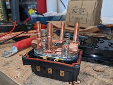
Figure 6 - Welded relay. Only the right two studs were used.
Conclusions
When operating outside of the MRBF specs, conservatively expect at least the housing to fail and molten copper and plastic debris to fly around. This experiment is anecdotal only and needs to be repeated many times to show repeatability.
Recommendations
Marine Rated Battery Fuses (MRBFs) are sometimes used to replace Class T fuses due to supply chain issues, ease of installation, space constraints, and cost. However, the breaking capacity of MRBF fuses is significanly lower than that of Class T fuses as shown in Figure 1.

Figure 1. Ampere Interrupting Capacity vs DC Voltage Rating
Problem
How will an MRBF fuse behave when subjected to a dead short outside of the fuse specifications?
Background
If the fuse does not quench the arc, then hot plasma could theoretically turn the fuse into a near-perfect conductor and cause a fire, instead of a near-perfect isolator that prevents fire.
In a previous experiment, an MRBF fuse was blown using an LFP battery, and a relatively small diameter wire was used, resulting in a relatively large circuit resistance, so it may not be a conservative representation of many battery installations.
Goal
The goal is to create a practical, realistic, and relatively safe near-worst-case dead short experimental setup using a relatively large capacity (Ah) battery together with large-diameter and short-length conductors that can be used to observe how MRBF fuses behave when a dead short occurs.
Experimental setup
See Figure 2 for the experimental setup.

Figure 2. Experimental setup.
Parts used:
- MRBF fuse block and MRBF fuse rated 150A (random rating choice).
- Battery: 4 x brand new Victron Smart Lithium 330Ah 12V LFP in series, 48Vnom; never charged or discharged; NO internal BMS; Battery voltage = 52.7V = 3.29Vpc (SoC unknown).
- Battery interconnects ("busbars"/ battery cables): 4/0 AWG UL-listed pure copper. Total cable length ~20" (500mm).
- Tinned copper lugs, hammer crimped on solid concrete substrate (one sample cut in half after crimping to verify quality which was good). Lugs degreased before mounting, torqued to spec.
- Dead short initiation device: 250A snowmobile winch relay (solenoid, approx 5Ω), triggered remotely with power supply set at 14Vdc.
- Backup circuit breaking methods in the order of prioritized use:
- Use extension pole tree branch cutter. This cutter was verified to cut like a knife through butter through copper cables. Once cut, the weight of the relay (black box with black tape in Figure 2) will pull down one cut end to create a gap large enough to quench the arc. Locally remove cable insulation to reduce cutting resistance.
- In case method (1) fails: Use a stand-by impact drill set to CCW rotation with socket wrench attached to disconnect interconnect bolt.
- In case methods (1) and (2) fail: Use manual cable cutter.
- Safety goggles; gloves; fire protective clothing.
- Fire extinguisher nearby especially for extinguishing burning insulation after breaking circuit.
- Second person with phone to call for help.
The initial calculated (estimated) theoretical dead short current is approx 14,000A (14kA). This is wel outside the MRBF specs as shown in Figure 1. The instantaneous theoretical dead short power is in the order of 700,000W (700kW), which roughly matches the maximum power of a Tesla Model S Plaid
Results
- The fuse successfully quenched the arc in the order of one video frame rate interval, in this case 30fps, so 1/30 = 0.033s. See also Figures 3 and 4.
- The fuse polycarbonate (assumption; probably not acrylic) housing back wall blew out and landed ~10 ft away. See also Figure 5.
- Sparks of molten copper blew out and landed 1-3ft away.
- The relay welded closed (this was expected) and had to be taken apart to break the contact points loose as shown in Figure 6.

Figure 3. This is what the fuse blowing looks like in close-up (most dramatic video frame).

Figure 4. Fuse blowing process.

Figure 5. The MRBF fuse after blowing. The separation occurred at the plastic weld / glue seam.

Figure 6 - Welded relay. Only the right two studs were used.
Conclusions
When operating outside of the MRBF specs, conservatively expect at least the housing to fail and molten copper and plastic debris to fly around. This experiment is anecdotal only and needs to be repeated many times to show repeatability.
Recommendations
- Repeat this experiment to evaluate repeatability.
- Vary the fuse current rating: A 300A MRBF fuse could yield different results.
- vary the battery SoC.
- Etc.
Last edited:


