diy solar

diy solar

JK 4S 200A BMS

I really don't get the hangup on the Paralleled Battery Packs using JK or any other respectable BMS. As long as the system is properly "built" with equal length wire, each pack is independently fused with the "correct" fuse there really should be no issues, many of us are doing it.

Batteries in Series has always been a challenge and moreso depending on the chemistry involved and that has lead to a lot of "bafflegab" and confusion. With the Battery Tech we are using here which is mostly LFP, there is little need to place batteries in Series unless people are purchasing Prebuilts and even BattleBorn has made this clear as to limitations and they actually support limited Series Batteries. Below is an extract on Paralled Batteries.


There IS a GOTCHA with Parallel Packs in a Bank and this is what I believe is the underlying troublespot here.
Example: If a bank of 3 packs is running along and is at 75% and 1 pack disconnects for whatever reason, the other two will continue and take the extra charge/discharge without consideration. The "down" pack will remain at 75% until the problem is resolved (unless the failure is draining it). Once corrected and being put back "online" the SOC Differential can create havoc within the bank resulting either in a Surge out if the other 2 packs are at a lower SOC or a large surge inbound from the 2 packs because they are at a higher SOC. In Both of those instances, the Instant Rush can exceed the individual BMS capabilities resulting in Damage and even releasing the Magic Smoke.

This is one of the major downsides of using FET Based BMS', as Relay-based ones just drop the Relay/SSR instantly when required, disconnecting the pack and no FETS get smoked. In that instance the Relay/SSR Capacity is the limiting factor and which can be 200-1000A or more and why they are used in EV's that push/pull a lot of juice.
Problem even with fast-acting Class-T fuses or SSR Relay is in rush current that can easily fry mosfet or SSR. And no communication between BMS in parallel setup. There are required good software algorithm for rhis to work and never let one bank if kicked out from rest of battery banks back online. Time for fast-acting Class-T fuses is enough to fry mosfet type BMS. I would advise on BMS that don't use mosfet and integration of fast-acting Class-T fuses as last defense. Regarding resistance with additional fast-acting Class-T fuses and Relays are sacrifice for safety that are easily dealt with. Now regarding EV battery packs and SSR Relays there is very strict software algorithm that will bring current draw down to safe limits before breaking down convention. And there is another layer of safety that use Pyro fuses that will brake connection if current cannot be lowered before cutting down power under high current demands. Mosfet type BMS should be substitute but not real way to manage multiple banks in parallel for full time off grid battery setup.
I could get on fire by other people here for what I suggest but I will be more than happy to answer any questions. Safety should be over anything else especially if you are using many parallel battery setups.
 
Pyro fuses can be easily salvaged from EV salvage yards and some BMS out there have ability to setup this type easily. From my knowledge Batrium is one of them....probably more that i didn't have time to research. Infineon technology is what I'm very familiar with but this is another discussion.
 
Wink Wink Nudge Nudge I use MRBF Fuses. They had been connected to Battery Pack terminals, Now they are on the Busbar with my new config.
I've never had a problem, but then again the Busbars are fed to a Midnite E-Panel with a Monster 250A Breaker.
REF to the 250A Breaker:
 
Problem even with fast-acting Class-T fuses or SSR Relay is in rush current that can easily fry mosfet or SSR.

I actually tested this. With a class-T fuse in each bank, I shorted the output of 2 paralleled 48V packs, each with a 100A JK BMS. Multiple times. Cost me a lot of money in Class T fuses (maybe this explains the current shortage) ;)
Both BMS are still running without issues today.
 
I actually tested this. With a class-T fuse in each bank, I shorted the output of 2 paralleled 48V packs, each with a 100A JK BMS. Multiple times. Cost me a lot of money in Class T fuses (maybe this explains the current shortage) ;)
Both BMS are still running without issues today.
I have not tested this with this BMS but if this BMS can survive in rush current before fast-acting Class-T fuses burn out that is cool. But still is happening over mosfet and danger of having BMS going bad vs independent BMS module that uses heavy duty industrial-rated relays or other ways to trip high in rush current. Once Pyro fuses becomes available for aftermarket it will change how this battery systems are built .
 
Initial test of new "Low Temperature Heater function": The BMS provides this function with no issues, running a heater pad at 2.9A for multiple minutes.

For this test, I attached a single "motorcycle seat" 12V heating pad, between the "12V" main output of the 4S test battery and the new 5-wire connection lug from the heater port. (This one: https://smile.amazon.com/gp/product/B084YXXM2P.) This pad is capable of 2.9 on that circuit, while running at its own "high temperature" setting. (I had first connected it to the main 12 main "P-", to verify that it would not exceed 3.0 Amps on coulomb counter, at the test battery voltage of 13.30 Volts).

Removing the temp probes from the battery pack, I inserted those a probes into a glass of ice to provoke "low temp charging shutdown". I had previously set non-default values of 5.0 C for shutdown, and 8.0 C for recovery. The charging CMOS was immediately disabled, with a blinking "low temperature" warning appearing on the Android App. The warming pad circuit was immediately enabled, with that 2.9A "heating pad current" show as a discharging value. The pad became warm, and cycled a couple of times from its own temp Sensor circuitry. The BMS "heater circuit" handled those stops and starts (within the downstream "heater pad) with no issues.

I am uncertain whether the output CURRENT and POWER limits (which have already been documented for this interface interface), can be protected from an over-current configuration by the BMS itself. To create such a test (for slightly more than 3.0A), I can a 2nd resistor in parallel with this heater pad. I will await confirmation from Nami (regarding the presence "3A" over-current protection within the BMS itself) before doing that.
 
Last edited:
My bluetooth is stuck on on the BMS and now I can't connect to it. Probably because I was trying to get the iOS app to disconnect from it but couldn't so I turned bluetooth off on the phone and now BMS still thinks it is connected to phone but phone can't connect to it now. Is there simply way to reset the bluetooth? I didn't want to pull the balance cables since I assume that would cut power to my inverter.
 
My bluetooth is stuck on on the BMS and now I can't connect to it. Probably because I was trying to get the iOS app to disconnect from it but couldn't so I turned bluetooth off on the phone and now BMS still thinks it is connected to phone but phone can't connect to it now. Is there simply way to reset the bluetooth? I didn't want to pull the balance cables since I assume that would cut power to my inverter.
Do you have either the basic power switch or the small GUI power switch (button on the side), so that you can RESET the BMS without pulling the BMS header?

If not, pulling the BMS header alone (and letting the BMS "loose power" for about a minute) Might enable you to use my old "interface-free" Daly method: (1) pull the balance/power header; (2) plug it back in; (3) put a charger between main battery "+" bus and the and the "P-" bus negative bus,

I've restarted my "new-to-me" JK about 10 times, using both of the power switches, just for the heck of it - and to see that settings are retained.
 
Do you have either the basic power switch or the small GUI power switch (button on the side), so that you can RESET the BMS without pulling the BMS header?
Thank you so much! that worked with the GUI power switch and I didn't lose power
 
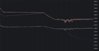
Any ideas why this one cell (blue) does not appear to be getting balanced? I see the one purple one did properly get balanced. I changed the balance threshold to 3.1V to make sure everything was in range to enable balancing.Screen Shot 2022-06-04 at 1.06.57 PM.png
 
My bluetooth is stuck on on the BMS and now I can't connect to it. Probably because I was trying to get the iOS app to disconnect from it but couldn't so I turned bluetooth off on the phone and now BMS still thinks it is connected to phone but phone can't connect to it now. Is there simply way to reset the bluetooth? I didn't want to pull the balance cables since I assume that would cut power to my inverter.
Have inverter on idle use jumper cables while you rebooting BMS. Just my advice.
 
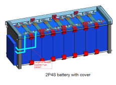
Can anyone tell me how long the 7ga leads are that Hankzor is providing for connection to the B- and P-? I plan to mount the Jk to the end cap of my build and hope that they will reach form both - terminals to the BMS.
 

Attachments

  • cable length.png
    cable length.png
    212.3 KB · Views: 25
Can anyone tell me how long the 7ga leads are that Hankzor is providing for connection to the B- and P-? I plan to mount the Jk to the end cap of my build and hope that they will reach form both - terminals to the BMS.
See this post:
 
See this post:
Do you know how long the 7ga wires are? I will not have any high demands so am happy with the 7ga size and the suppleness is nice. my biggest load is a 500W invertor so nothing major.
In the post supplied, I see 10cm but that is not the 4s. Do they all have the same length? If it is that short, I will probably need to make a couple of new leads because it does not make sense to have bolted on leads with a splice when I only need maybe 8" total.
 
Last edited:
Do you know how long the 7ga wires are? I will not have any high demands so am happy with the 7ga size and the suppleness is nice. my biggest load is a 500W invertor so nothing major.
In the post supplied, I see 10cm but that is not the 4s. Do they all have the same length? If it is that short, I will probably need to make a couple of new leads because it does not make sense to have bolted on leads with a splice when I only need maybe 8" total.
If you are referring to the new 4S version they have threaded holes where you supply your own cable and lugs which I think is better.
 
Do you know how long the 7ga wires are? I will not have any high demands so am happy with the 7ga size and the suppleness is nice. my biggest load is a 500W invertor so nothing major.
In the post supplied, I see 10cm but that is not the 4s. Do they all have the same length? If it is that short, I will probably need to make a couple of new leads because it does not make sense to have bolted on leads with a splice when I only need maybe 8" total.
Thy're quite short, maybe around 5" long. But they're definitely longer than 10 cm each). If you need more length (B-, or P-, or both sets) you can make bigger terminal wires with more copper, at the length of you need. On my own 230Ah 4s battery pack, I will upgrade both sides to at least dual AWG-2, and perhaps a bit bigger than that. Tinned lugs for all connections.
 
My current battery cables are 2-O which is incredibly oversized given that they only significant current is from the 105 Amp alternator with a 10' run at most. They are too stiff to make the turns that will be needed to get from A to B.
On this build, I will eventually have a 1200W invertor as the max load.
My 2/0 has ~1300 strands which just barely allowed me to make a looping turn from the T fuse mounted on side of battery case to the positive on the battery.
 
My 2/0 has ~1300 strands which just barely allowed me to make a looping turn from the T fuse mounted on side of battery case to the positive on the battery.
Wow! How long did it take to count them?!?!? :eek: ;)

Given that I have two cell terminals and two BMS lug connections, I plan to use two conductors from the cells to BMS to the ground shunt. All of my conductors between the house bank and the alternator are 2-O. If I want two conductors that equal the cross-section area of a 2-O I will need to use two #2 AWG if my math is correct.
Am I looking at this correctly?
 
Back
Top