diy solar

diy solar

JK-BMS-CAN with new Cut-Off Charging Logic (open-source)

Also, I'd like to add my two cents to this amazing project.

I've prepared a summary connection diagram for those who are going to use the M5Stack—a nice product that simplifies the wiring and connections, making the hardware part almost plug and play.
Both configurations have been tested and are stable

View attachment 198115
1. Do you have a link to purchase these components
2. would one be able to use more than 1 battery set (i.e parallel 2 batteries) ?
3. which yaml code did you use for this , or this is not a ESP dev thing?
 
Also, I'd like to add my two cents to this amazing project.

I've prepared a summary connection diagram for those who are going to use the M5Stack—a nice product that simplifies the wiring and connections, making the hardware part almost plug and play.
Both configurations have been tested and are stable

View attachment 198115
@arzaman between the esp32 dev board and the M5 stack, agree M5 is extremely simple. Confirmed this works on my EG46000xp with 1.16.4.

Just ordered two more. Really want to get the Victron shunt reporting to CAN. From the other project I’m already reading SOC, V and current (A) on the standard ESP dev board from shunt.
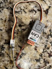
IMG_4464.jpeg
 
@arzaman between the esp32 dev board and the M5 stack, agree M5 is extremely simple. Confirmed this works on my EG46000xp with 1.16.4.

Just ordered two more. Really want to get the Victron shunt reporting to CAN. From the other project I’m already reading SOC, V and current (A) on the standard ESP dev board from shunt.
Do these M5stack adaptors have a 120ohm termination resistor with them? Just thinking ahead to a multi-BMS solution where there may be more than 2 BMS to CAN adaptors.
 
Do these M5stack adaptors have a 120ohm termination resistor with them? Just thinking ahead to a multi-BMS solution where there may be more than 2 BMS to CAN adaptors.
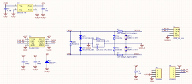
No there is no 120ohm termination

this is the schematic
1708810662239.png
 
1. Do you have a link to purchase these components
2. would one be able to use more than 1 battery set (i.e parallel 2 batteries) ?
3. which yaml code did you use for this , or this is not a ESP dev thing?
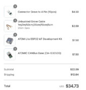
Here the link to main components

CAN BUS base
ATOM S3 Lite module
Suggest also to buy an adatper to solder the cable from JST1.5mm from JK-BMS

there is also official aliexpress store if is more convinient for you

the mangement of multiple BMS depends on the SW more than HW !

code use the last version 1.17.3
O.k thanks a lot for the details

so if I get you right.

No Flashing of Codes to these Modules>?
and no hope for Multi Battery parallel connection?

Regards
 
exactly same ESPhome FW compilation and uplad procedure as per ESP32 dev boards
just update in the yaml file the CanBus and TX/RX pin assignement as per my schema


as I wrote is not only a matter of HW !!
Please elaborate for a newbie - as I wrote is not only a matter of HW !! ??

i am just placing my order now - want to make sure i order it all at once if i need an extra module to archive the parallel connection, please also include link..

thanks
 
O.k thanks a lot for the details

so if I get you right.

No Flashing of Codes to these Modules>?
and no hope for Multi Battery parallel connection?

Regards

There is a way to do it, the code needs to be developed and tested (likely with you as a tester).
I would suggest buying the M5stack setup, then when higher priority features are finished, you'll be ready to test multi-BMS comms with minimal delay.

To make it as clear as possible:
- One ESP32 with CAN adaptor will be needed per BMS.
- Code for multi-BMS support is not developed yet, but I have ideas on how to do this.
- There is no timeline for multi-BMS support at this point.
 
There is a way to do it, the code needs to be developed and tested (likely with you as a tester).
I would suggest buying the M5stack setup, then when higher priority features are finished, you'll be ready to test multi-BMS comms with minimal delay.
Sure - i am up for it...
 
Also, i am hoping that we don't have an issue with the JK2a24s15p model on the RS485 ports for this project - otherwise, i would have to order the xxx20p as i don't see anyone else who has reported success with my version.

@MrPablo
Do we have a list of confirmed JK modules that have worked on both Wire and BLE?
 
Here the link to main components

CAN BUS base
ATOM S3 Lite module
Suggest also to buy an adatper to solder the cable from JST1.5mm from JK-BMS

there is also official aliexpress store if is more convinient for you

the mangement of multiple BMS depends on the SW more than HW !

code use the last version 1.17.3
I have ordered the components x 2

thanks..

Edit:
Question - does the M5Stack Official ATOMS£ has the ability for wired connection too, or do i need to order the M5Stack Official ATOM ESP32 separately
 
Last edited:
Also, i am hoping that we don't have an issue with the JK2a24s15p model on the RS485 ports for this project - otherwise, i would have to order the xxx20p as i don't see anyone else who has reported success with my version.

@MrPablo
Do we have a list of confirmed JK modules that have worked on both Wire and BLE?
You can see a list of supported devices in this repository - we use this repository for the code that communicates with the BMS itself.
 
What the logic that would stop the system from discharging beyond a certain point - say beyond 50 40 %

i ask bcos i have not been able to discharge my battery to 0 percent since commissioned.

is there a setting that controls this...i have checked the JKBMS app, its definitely enabled otherwise it wouldn't have been discharging this afternoon between 100 and 50 %

i am suspecting the Solis or the ESP32 settings somewhere...
 
Back
Top