You are using an out of date browser. It may not display this or other websites correctly.
You should upgrade or use an alternative browser.
You should upgrade or use an alternative browser.
JKBMS and wire resitance
- Thread starter Paulfrench35
- Start date
BentleyJ
Solar Wizard
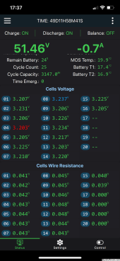
Values are the calculated internal resistance of each cell. If a large deviation appears on one cell it could indicate that cell is failing. Keep in mind the value would also include any problems with the wire and/or connections at the wiring harness plug and at the battery itself. Those should always be checked first before assuming the cell is bad.
Paulfrench35
New Member
BentleyJ
Solar Wizard
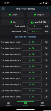
Yes, those are the calculated values for total wire resistance of the cells & wiring. I re-read your first post and realized you were asking about a different menu item. Not sure, but it looks like it is a calibration form where the user can input the resistance of the wires and connectors so this amount gets subtracted from the calculated value thus showing true cell resistance values?
Hopefully some of the other JK BMS users can clarify this for us. I'm using the stand alone 2A Bluetooth balancer. It has the Cell Wire Resistance values but not the item shown in your first post.
Hopefully some of the other JK BMS users can clarify this for us. I'm using the stand alone 2A Bluetooth balancer. It has the Cell Wire Resistance values but not the item shown in your first post.
Steve_S
Offgrid Cabineer, N.E. Ontario, Canada
The values shown on Page-1 are for the cell leads to the terminal and calculated by the BMS. Your numbers are very good BTW, pretty hard to get much better than that.
On the settings page, you can override the values IF required but you'd need a really accurate multimeter to test each wire. I've not seen anyone need to do so.
On the settings page, you can override the values IF required but you'd need a really accurate multimeter to test each wire. I've not seen anyone need to do so.
Paulfrench35
New Member
Yes, I'am talking about this.Not sure, but it looks like it is a calibration form where the user can input the resistance of the wires and connectors so this amount gets subtracted from the calculated value thus showing true cell resistance values?
Paulfrench35
New Member
BentleyJ
Solar Wizard
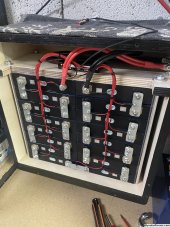
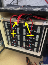
No they don't have to be the exact same length. Based on the pic they are a short length so wire resistance is negligible as long as they are sized properly for the amperage.
The exception to the above is with multiple batteries connected in parallel to a bus bar then the cables should be the same length.
The exception to the above is with multiple batteries connected in parallel to a bus bar then the cables should be the same length.
Paulfrench35
New Member
In the case of several batteries, cables of different lengths cause what problems?
Steve_S
Offgrid Cabineer, N.E. Ontario, Canada
Various things can occur but mostly imbalanced charging. Unlike Lead Acid based chemistries which are "Brute Force" all Lithium Chemistries are actually Millivot & Milliohn sensitive (hence the fancy BMS'). Equal Length battery cables & consistency is quite important especially when dealing with paralleled packs. You can run packs with different AH's ie 230, 280 & 304 together quite easily, larger differences (over 100AH) require some fancy math and working out averages for things like EndAmps/TailCurrent and understanding that they will charge & discharge proportionately in relation to their capacities.In the case of several batteries, cables of different lengths cause what problems?
RCinFLA
Solar Wizard
- Joined
- Jun 21, 2020
- Messages
- 3,574
It is calculated from a balance current pulse push.
It is not super accurate but good enough to detect a bad sense wire connection. The measurement will be less accurate the more you back down balancing current setting.
It is easy to snag a sense wire and pull it out of its connection terminal lug. A bad bus bar connection may also be detected in the measurement, but it would have to be a really bad bus bar connection like forgetting to tighten down a lug nut. When you see a single abnormal resistance, first thing is to check bus bar connection before focusing on sense wire connection.
Normal cell voltage measurements momentarily shuts down any balancing current during the cell voltage sampling to avoid sense wire voltage drop from balancing current that would impact cell voltage measurement by BMS. This is a common practice for even low balancing current BMS's.
There is a limit to how much the sense wires series resistance can be before their resistance starts to impact the balance constant current circuitry controlling the amount of balance current delivered. If sense wire voltage drop gets too great the DC-to-DC boost converter creating the balance current will hit its maximum allowed voltage boost causing less than target balance current to be delivered.
Berseker
New Member
- Joined
- Mar 22, 2020
- Messages
- 273
Just a general jk bms question..
my bms didn't come with neg and pos cables. is there a limit to what length of cable, I can use on the bms?
presently I have 35mm 7 inch and 9 inch for the p & b ports, I recall the OEM cables on some jk bms models are only 3 inch or so, hence why am wondering if the longer cables on mine would cause an issue
chaosnature
New Member
- Joined
- Sep 15, 2022
- Messages
- 527
Hi All
any one know why we are getting all unknown values even though the CAN is o.k?
View attachment 196537
The Bluetooth code works - suggesting it has to be the GIO Pins wrong, i have tried 16/17 and 01/03 and even swapped them around.
please advise
regards
any one know why we are getting all unknown values even though the CAN is o.k?
View attachment 196537
The Bluetooth code works - suggesting it has to be the GIO Pins wrong, i have tried 16/17 and 01/03 and even swapped them around.
please advise
regards
Similar threads
- Replies
- 18
- Views
- 1K
- Replies
- 1
- Views
- 372
- Replies
- 3
- Views
- 245


