diy solar

diy solar

Just a bit confused - Nissan Leaf Solar battery set up

That was the plan, Thank you, that's reassuring as I was nervous to plug everything in for fear of damaging something.
If I use a direct bolt on fuse on the battery end of my main positive wire would you use a 40A fuse or something different im having trouble understanding how to size that one.

If I am understanding this correctly once the solar charge controller is set up with the correct parameters I will be able to also hook up my inverter to this system, and it seems that I would wire that directly to my main pos+ and neg- terminals.
Would I then fuse that wire as well to provide extra protection for the inverter?

While certain parts of this seem in my mind to be coming together, I am concerned, or still perplexed as to how the rest of my envisioned system comes into play.
Should I be sending the majority of my large negative and positive loads to a bus bar with multiple terminals coming from my main battery wires?
Or should I run circuits off of my battery to wire up a fuse box and loads to that?


Again Thank you so much for all of the help.
 
Think of it this way....from now on the battery connection is "The negative is the stud where my black wire is. The positive is the main positive on the bus bar".

If it were me, this is what I would do. (also trying to put myself in your shoes)
1. Get the Bluetooth working so you can see what the BMS sees. You can make sure the BMS is connected and monitoring the cells.
2. Connect your Inverter and turn it on (no load) to make sure it is working. Use a resister to precharge the inverter. Maybe load it with a light or two. You can monitor the battery with the BMS app. You should see discharge amps on the BMS app because the battery current to the inverter will be going through the BMS (black wire). The BMS could kill the inverter if a cell gets too low, part of the design of the system. (turn the invert off)
3. Connect the battery connections of the solar charger. Again this will run through the BMS, connecting to that stud with the black wire. Program the solar charger
4. Connect the solar panels to the charger. You might to just use one panel at first or start early in the day when there is no light. Monitor the charger. It will tell you the amps going to the battery. Monitor the battery with the BMS app, it will also tell you the charging amps.
5. When the battery is charged enough for heavier load testing, turn the inverter back on and do some tests.

Have fun.
 
Ok this definitely makes a clear idea for me of what to start with.
I really appreciate you helping me so much DThames.
I am a little unsure of exactly how to precharge the inverter with a resistor though ill try to look into and understand this more.

Also the BMS being able to kill the inverter because a cell gets too low wouldn't happen just from plugging in the inverter itself, it would happen with loads connected right? Once the BMS is hooked up and functioning, I should know the charge state of the batteries I assume.
And I am not sure I understand the process of bottom balancing/ top balancing batteries, but I think this is to prevent any one cell from discharging or charging faster than one of the others.
Is this something I need to figure out and do before I begin using this system?

And just so i can understand a little more, i have currently two solar panels paralleled on the roof coming down with the negative and posative wires capped and not connected to anything currently. I could easily enough pull some connections and make it just one 100W panell connection ready for when I do hook up the solar but I am curious what the benefit or reasoning for that would be? Lower voltage, less risk?


I will also be using that 50A DCtoDC charger and could hook this up with the van's main battery to also charge the battery bank up/ I believe the inverter is also a charger and should allow me to charge my system off normal housing power, just thinking out loud, these may be faster or more efficient than charging with the solar during this time of year anyway haha.

Thank you!
 
Last edited:
Fusing is sort of a personal choice. Myself, I would put in a slow blow that was equal or a little greater to what the inverter should see under a surge. condition. The inverter should shut down from over current. The BMS should shut down from over current. If all of your cables where protected from possible damage you really don't need a fuse, in one sense. But a fuse is there in case something really unexpected happens. You don't want to blow the fuse just because of a current spike within some odd usage cases. You do want to fuse to blow if wires are crushed/shorted, or one of your other current limit devices has a meltdown.

What is your expected peak inverter amps?
 
Ok safety and function first so I will be adding a fuse, with this 2000W inverter my main loads would be a laptop charging, occasionally charging my wireless power tool batteries that are 18v and 1.5 to 4AH batteries.(60Hz and 60W or 60Hz and 50W) Didnt see an amp draw rating on the charger. But even the few corded tools i have have something just over 4Amp draw. Very rarely i might run a little blender. But all of my lights, my little fridge and a majority of my other appliances will be able to be charged or powered with just 12v power.
 
And the manual for the inverter says its Charger specifications include an output current of 5-65A (configurable at 5A intervals)
And mentions Transfer switch specifications - Transfer Relay Rating - 30A Maximum Bypass.
 
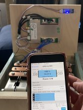
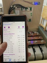
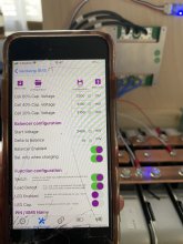
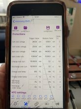
BMS hooked right up and started reading, i went into the settings and hit the "Read BMS".
I assume this is accurate but it says number of cells at the top (4) and I have 6 battery modules. Is this because this is a 4s BMS? Or is this a parameter I should change.

IMG_5851.jpg

IMG_5852.jpgIMG_5853.jpgIMG_5854.jpg
Will I need to pick up a simple battery tester or something like that to confirm what some of these should be set to?
I am also going to pick up a 25w 30ohm resister so I can precharge the inverter.
Also for the fusing of my main positive terminal I am planning on finding either a slow blow or bolt on fuse that's 65A because that would be the high end of a surge I'm thinking and if I'm not normally pushing the limits of this system I think that would just be a good extra protection for worst case scenarios.
 
You definitely want a fuse on the battery. If there is a short somewhere a fuse can keep you from having an incredibly bad day. I would also put a circuit breaker between the solar panels and the solar charge controller. This offers some protection and a way to turn off the solar panels if/when needed.
 
Yeah I'm all about adding safety, I'm certainly not a professional so more safety switches and fuses sounds better to me.

Looking into it it seems that solar panels, two 100W panels individually have somewhere around 6amps during peak sunlight hours. But 200w brings in just over 11Amps, I think a reasonable choice would be a 15A circut breaker like this.

And i have a 200amp fuse coming for my main positive, basing that on my 2000W inverter. Its not a slow blow fuse - but comes with housing and an extra so that seems like it would work well for me.

Would it be a good idea to add another 60Amp circuit breaker for my 50A DCto DC charger, i suppose that would be another added protection between the device and battery bank, and again like you mentioned, allows me to turn this off if I need for some reason. Does it seem like overkill or just very safe to then add one more between the solar charge controller and battery, that one I would size at 50A because its a 40A solar charge controller.
 
Ok, Thank you Bolo, I agree with that an would always rather have it and not need it than need it and not have it.
With that said I have this 200A fuse that will be in line with the main pos+ wire.
After some consideration it seems i have two viable ways to begin this setup.
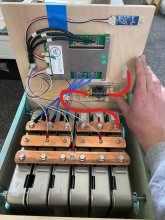
This one i create another post to base my Pos+ wires off of. This to me seems like it could get messy having tons of connections coming to the battery box, and all the connections would be stacked on each other.

posterminal1.jpg
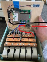
And number two- Sending both lines directly to a couple multipost busbars or distribution blocks and having everything stem from there outward- This looks much cleaner and seems in my mind like it would work.
posterminaldirect.jpg

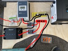
wiring01.jpg
If I go this route can I then just wire the inverter to the busbars as well? Or should that be going directly to the battery on its own fused line?
I have a resistor to precharge the inverter before i plug in.
Though I am still a little confused on my fuse box, would it be ok to just wire that off the bus bars as well?

Also I am realizing I should probably have a another 60A fuse for the DC to DC charger- probably right next to the battery in the vehicle. So ill plan for that as well.

Mounting some 2x3's on the back recessed into the wall space for extra support behind that inverter, thing is like 50lbs.
 
Now with a little more inspection, I see that even a 250A bus bar would only be capable of 20A a stud connection, is it then more reasonable to just stack my main components wires on a single terminal pole together ( option one pictured above in last post) or get something more like a 500A bus bar, that might be able to accommodate the individual components capabilities better?
I am also planning on adding a couple of high amperage battery shutoff switches, I believe ill put one on the main battery wires, allowing me to shutoff everything from the main battery's, and one between the vehicle battery and the DC to DC charger in case I want to disconnect or turn that off easily.
 
Any input would be appreciated on this, or reference to where i could try to understand this better.
It seems like I am supposed to have my inverter directly wired to my battery, with a 200A fuse as protection. Should I also have a battery shutoff specifically for this? Or is it not needed because it already has a switch to turn on/off the inverter alone. Can everything else go off of a distribution block like the one i linked below?

Or Can i run 2awg wire with a battery shutoff switch, and 200A fuse to a 4gang distribution block kind of making that my main positive, and then just use 4 gauge off of that for the other components?

Just feeling overwhelmed a little with the small details, I have been trying to understand whether or not I need a shunt in my set up as well or if there is one in my BMS or other components.
 
Well I precharged the inverter with my little resistor and didn't see any sparks so that seemed good. But as soon as I powered up the inverter I got a loud beeping alarm that would not turn off, Fault light indicator, and error code 99. Manual shows this as likely being the "Inverter fail to slow start".
Contacted Renogy they didn't seem to have much to say about the error code, and asked for photos of the system to try and help so ill be trying to send those over to them right away.
 
So it appears third inverter is the charm from renogy- I have finally gotten a box that was in decent condition and the renogy staff went through everything they could and we confirmed it was a bad inverter.
Yesterday i hooked up the new one, and was thrilled to see it work and function properly added a light, charged a little of my phone just to see the change in currents in the app.
I also finished a side project of installing a diesel heater into the van as well and because it already had a inline fuse I thought why not add that on to the battery.
This morning i turned on the heater running off the battery directly somewhere around 96% on the BMS and still running over 12V - the inverter is not hooked up right now, just mounted on the wall.

After approximately 1.5 hours I was climbing into the rear of the van fairly warm and toasty I decided to turn off the heater while I was going to hook up the inverter again and when I checked the BMS as the heater was powering down I was shocked to see a really low reading on the battery of 0% but it was still powering the heater??? How is this even possible? Or is this more likely a BMS issue?
Now im worried about hooking up the inverter again because as was mentioned above that could kill the inverter.
Would it be appropriate to hook the inverter up to a house outlet- its an inverter charger, and turn it on while its connected to 120, so it can use shore power and charge the batteries back up? Or should I wait until I have the solar charge controller hooked up, programmed, and have it charge the batteries with Solar?
Ill be trying to download and program the charge controller today and tomorrow likely. Though i am not entirely sure how to program this, and slightly unsure of why ill have to. If my system says 14.15 or so around 100% wouldn't I be able to just set everything to Lithium and let it charge away at 14.7 or whatever is preset.
 
If my system says 14.15 or so around 100% wouldn't I be able to just set everything to Lithium and let it charge away at 14.7 or whatever is preset.
If you are using Nissan Leaf Modules 14.15 volts seems low to me. Confirm how many modules you have? The voltage range I used per module was 7 volts and 8.3 volts. Not all Lithium chemistries are the same so a generic Lithium setting may not work for Nissan Leaf modules. I had to buy a specific Renogy Inverter that would go up to 16 volts to use two module groups for a back up for my sister's house.
 
I have six modules total in my system and at 100% it was reading in at 14.21 in my 4 cell BMS it reads 3.5v each cell. and now seemingly out of nowhere somewhere along the time it was running the diesel heater it jumped down to 0% battery 11.69v and each cell is reading only 2.92v.
And i believe the Renogy inverter charger i got as well as every other part of my system has a USER mode so everything could be adjusted, would I be setting everything just to charge at the exact max volt?
I cant understand why or how it dropped so fast though- watching it run the night before it certainly should not have dropped so quickly.


Also feeling a little at a loss- how can I add power back into these batteries safely? Can I just plug the inverter into house power and then wire it up to my battery bank and let it charge it up?
 
I have not set anything to charge anything to any point. Because I did not and still do not entirely understand what they are even supposed to be charged to I set the inverter to Lithium when I first turned it on, and did nothing else with it. I did not even try to charge the batteries because I just assumed 100% on the BMS meant that it actually was still 100% How do you normally charge your pack of batteries safely? Cause I could either try to hook up the inverter with it connected to shore power and then i could try to program the inverter to user mode and just go to 16v on that-
 
or Are those parameters I should be setting in the BMS? or in each part of my system.
And again I have extreme worries about hurting some part of my system, I just don't really understand the batteries and what they need and frankly I am freaking out thinking I might have damaged something.
 
Back
Top