diy solar

diy solar

Kisae DMT1250 partial disassembly and remote disconnect addition

Sipma02

New Member
Joined
May 27, 2020
Messages
141
I've done a lot of research and thinking of how to set up the best solar/DIY LFP system that I can for our Sprinter install. For reference, we'll have ~400 watts of solar and 280ah of LFP. In my research, I was inspired by @Craig 's method of using the Chargery to shut off his Solar Charge Controller and not even have a relay/DCC that draws power. That said, the SCC that I'm using also accepts alternator input. So sure, I could have wired in a separate port contactor or relay of some sort. But I noticed there is a manual shutoff switch on the bottom of the DMT1250, and it's just a simple on/off switch—two wires.

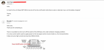
So I emailed Kisae to see if that was a safe method to shut down the controller. It was totally kosher!
DMT1250.png

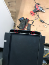
So I carefully took the unit apart. Flip the unit over. I started with these screws:
Screen Shot 2020-12-04 at 8.40.32 AM.png

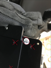
Then, I removed 2 screws on the back. Unfortunately, you'll have to remove this little sticker (circled in red, probably a warranty thing:mad:). The other screw is the on the opposite side to the screw below:
Screen Shot 2020-12-04 at 8.45.25 AM.png

Do not remove the screws on the X's. That was for testing purposes :)

You should have 4 screws removed.

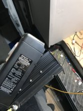
Gently pry off the cover. A flatblade screwdriver is helpful. You'll have to disconnect a small, simple connector to disconnect the display screen (mounted to the cover) from the rest of the body:
IMG_4266.JPG

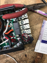
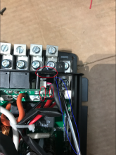
This next part is tough to see. The 2 small red circles are the wires are are going to solder on to. Topmost red circle is the switch itself. The blue circle (oval?) is my screwdriver. I used that to gently pry the switch out:
Screen Shot 2020-12-04 at 8.48.36 AM.png

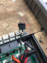
Now the switch is and about! If you are extremely nimble-fingered and good with a screwdriver, you might be able to get the switch out without disassembling the unit.

If you are bold and handy enough to attempt this, I'm sure you already know to push these tangs in to remove/release the switch:
Screen Shot 2020-12-04 at 8.51.00 AM.png

Now, we solder.
Screen Shot 2020-12-04 at 8.52.27 AM.png

It's not the best solder work I've done, but you can see I've soldered a 18awg wire on the switch leads. The other end of that 18awg wire will go to a small, Normally Open relay. The Chargery HVD will control the relay, and will power the relay to connect the 2 wires. If the Chargery cuts off due to high voltage; it will cut power to the relay, which will turn the unit off and stop charge to by pack. Since this is wired in parallel, the OEM shutoff switch will work normally. That switch will be turned off, so the relay (and therefore Chargery signal) can control the on/off of the DMT1250.

And since this is switching less than .5 amps, you can find the SMALLEST, lowest power draw relay ever!

Reverse the steps to reassemble. Hopefully this helps someone with their system!
 
Last edited:
Hi there, novice diy builder here so please be gentle with me.
Are you using the bms to switch the scc of when the bms shuts down due to batteries being fully charged? Is that even possible? I was planning on just using the switch and doing it manually n summer as I don’t want my batteries sitting at full charge for 8 months of the year
 
I'm not 100% sure I understand your question. Yes, the BMS shuts down the charger (Kisae DMT1250) when the BMS senses the cells are fully charged. Depending on the BMS, that is configurable. So if you want it to turn off charging when your cells are at 80%, you can set that up.

Does that answer your question? :)
 
I've done a lot of research and thinking of how to set up the best solar/DIY LFP system that I can for our Sprinter install. For reference, we'll have ~400 watts of solar and 280ah of LFP. In my research, I was inspired by @Craig 's method of using the Chargery to shut off his Solar Charge Controller and not even have a relay/DCC that draws power. That said, the SCC that I'm using also accepts alternator input. So sure, I could have wired in a separate port contactor or relay of some sort. But I noticed there is a manual shutoff switch on the bottom of the DMT1250, and it's just a simple on/off switch—two wires.

So I emailed Kisae to see if that was a safe method to shut down the controller. It was totally kosher!
View attachment 29279

So I carefully took the unit apart. Flip the unit over. I started with these screws:
View attachment 29280

Then, I removed 2 screws on the back. Unfortunately, you'll have to remove this little sticker (circled in red, probably a warranty thing:mad:). The other screw is the on the opposite side to the screw below:
View attachment 29282

Do not remove the screws on the X's. That was for testing purposes :)

You should have 4 screws removed.

Gently pry off the cover. A flatblade screwdriver is helpful. You'll have to disconnect a small, simple connector to disconnect the display screen (mounted to the cover) from the rest of the body:
View attachment 29283

This next part is tough to see. The 2 small red circles are the wires are are going to solder on to. Topmost red circle is the switch itself. The blue circle (oval?) is my screwdriver. I used that to gently pry the switch out:
View attachment 29284

Now the switch is and about! If you are extremely nimble-fingered and good with a screwdriver, you might be able to get the switch out without disassembling the unit.

If you are bold and handy enough to attempt this, I'm sure you already know to push these tangs in to remove/release the switch:
View attachment 29286

Now, we solder.
View attachment 29287

It's not the best solder work I've done, but you can see I've soldered a 18awg wire on the switch leads. The other end of that 18awg wire will go to a small, Normally Open relay. The Chargery HVD will control the relay, and will power the relay to connect the 2 wires. If the Chargery cuts off due to high voltage; it will cut power to the relay, which will turn the unit off and stop charge to by pack. Since this is wired in parallel, the OEM shutoff switch will work normally. That switch will be turned off, so the relay (and therefore Chargery signal) can control the on/off of the DMT1250.

And since this is switching less than .5 amps, you can find the SMALLEST, lowest power draw relay ever!

Reverse the steps to reassemble. Hopefully this helps someone with their system!
Hello fellow Minnesotan and thank you! I'm in North Branch and new to solar. I've done plenty of car audio and 120vAC work, but this is getting interesting.

Anyway, I am considering the DMT1250 myself for my older Class C. Is the red wire you added 12v in or is it grounded through the relay?

Also, what batteries are you using?
 
Hello! MN is awesome—we love it here. But actually, we are leaving to live in our van, full time, starting Sunday! MN will always be in our hearts :)

For something like a Class C where you could fit more solar, I miiiiiiight consider something different because the DMT1250 can only accept 50v input or 30a for a total of 500 watts. You can overdrive it to 600watts, but thats still not a ton. Just a thought.

Anyway, the red wire just gets connected to the black wire when the relay closes. Neither grounded or 12v! Just connects back to the other wire, completing the circuit and "turning on" the switch.

We have 280ah of DIY/Chinese LiFePo4 cells! Working great so far.
 
I’ve also got a dmt 1250 and was under the impression it could do 50a, the dmt1230 was the 30a version. I may have picked it up wrong but don’t have time just now to look in the user manual
 
I’ve also got a dmt 1250 and was under the impression it could do 50a, the dmt1230 was the 30a version. I may have picked it up wrong but don’t have time just now to look in the user manual

Good call, I wrote that too late at night. Yes, it can do 50 amps but has to be from the alternator. Even the DMT1250 is limited to 30 amps of solar.
 
I've done a lot of research and thinking of how to set up the best solar/DIY LFP system that I can for our Sprinter install. For reference, we'll have ~400 watts of solar and 280ah of LFP. In my research, I was inspired by @Craig 's method of using the Chargery to shut off his Solar Charge Controller and not even have a relay/DCC that draws power. That said, the SCC that I'm using also accepts alternator input. So sure, I could have wired in a separate port contactor or relay of some sort. But I noticed there is a manual shutoff switch on the bottom of the DMT1250, and it's just a simple on/off switch—two wires.

So I emailed Kisae to see if that was a safe method to shut down the controller. It was totally kosher!
View attachment 29279

So I carefully took the unit apart. Flip the unit over. I started with these screws:
View attachment 29280

Then, I removed 2 screws on the back. Unfortunately, you'll have to remove this little sticker (circled in red, probably a warranty thing:mad:). The other screw is the on the opposite side to the screw below:
View attachment 29282

Do not remove the screws on the X's. That was for testing purposes :)

You should have 4 screws removed.

Gently pry off the cover. A flatblade screwdriver is helpful. You'll have to disconnect a small, simple connector to disconnect the display screen (mounted to the cover) from the rest of the body:
View attachment 29283

This next part is tough to see. The 2 small red circles are the wires are are going to solder on to. Topmost red circle is the switch itself. The blue circle (oval?) is my screwdriver. I used that to gently pry the switch out:
View attachment 29284

Now the switch is and about! If you are extremely nimble-fingered and good with a screwdriver, you might be able to get the switch out without disassembling the unit.

If you are bold and handy enough to attempt this, I'm sure you already know to push these tangs in to remove/release the switch:
View attachment 29286

Now, we solder.
View attachment 29287

It's not the best solder work I've done, but you can see I've soldered a 18awg wire on the switch leads. The other end of that 18awg wire will go to a small, Normally Open relay. The Chargery HVD will control the relay, and will power the relay to connect the 2 wires. If the Chargery cuts off due to high voltage; it will cut power to the relay, which will turn the unit off and stop charge to by pack. Since this is wired in parallel, the OEM shutoff switch will work normally. That switch will be turned off, so the relay (and therefore Chargery signal) can control the on/off of the DMT1250.

And since this is switching less than .5 amps, you can find the SMALLEST, lowest power draw relay ever!

Reverse the steps to reassemble. Hopefully this helps someone with their system!

So the KISAE switch is in Off position and then is powered on by relay at the command of BMS.
With the switch in ON position it bypasses the relay and BMS control. I assume you considered the relay in series but then if that failed you could not defeat it using switch
 
So the KISAE switch is in Off position and then is powered on by relay at the command of BMS.
With the switch in ON position it bypasses the relay and BMS control. I assume you considered the relay in series but then if that failed you could not defeat it using switch
Spot on.
 
Yes, it can do 50 amps but has to be from the alternator. Even the DMT1250 is limited to 30 amps of solar.

Sorry for the necropost. I am reading about the DMT30/50-series units for an unrelated project.

The manual says both the 30/50 model are limited to 30A solar input:

Page 11
The charger limits the input current of CH2 to 30A maximum.

Perhaps that's what you meant.

I saw no mention of an output limit. Given MPPT's DC-DC conversion we would expect >30A on the output. They do give an example of 500W practical input max with nominal 12v panels. If we use their 97% claim it would pass up to 485W. So if it charging at 13.0v we might see something like 37A.

If it acts differently in reality that would be interesting to know.
 
Nice article.

I've just bought the Kisae DMT1250 & a 120A Avon LFP LiFePO4 battery and the 3-6 minute starter battery drain on stopping the vehicle engine is a real waste & a nuisance. It helps minimise the situation to switch back to the 5amp charge rate before turning off the engine, but this is a real pain to do without the optional remote display, with the DC-DC being under a seat and its' on/off switch under a screwed down cover!

Also the battery SOC is going down daily, another nuisance in that the DEC-DC is drawing 78 milliamps in standby constantly.

So your article looks great to sort both these things. Almost 3 years on now, is all still working ok? Have any implications raised themselves since?
 
Back
Top