diy solar

diy solar

Learner set up

a clip I watched so he was wrong too in explaining,
Yeah - There's a lot of that on the web, we all need to get better at quoting our sources.
At least when you try to quote your source, and it starts with "someone told me ... " rather than "the manufacturer of XYZ battery says ..." you can jolt yourself into rethinking the validity of the idea.
We could start another round of debate on whether MC4 connectors should be disassembled before installing, or left as-one as per the manufacturers instructions, but that's for another day.

I'm thinking that Kapati will get a cracker day today, its looking great all the way from Wellington to at least Kawhia
 
Ok done ,that 1 battery part came off a clip I watched so he was wrong too in explaining,

I have just changed to these settings and waiting for tomorrow, looks like hot day coming for Kapity coast
Yeh the 13.8 sounds good, Do I try do that or test other settings first
I think @Rednecktek was meaning the charging voltage should be 13.8, not the eq voltage, and your charge voltage is already 13.8.
Your charge controller will have (for lead batteries) three modes; normal charging (it outputs the "charge limit voltage", 14.6v for you), equalisation (14.6v for you), float (13.8v for you) and boost (13.2v for you).
As you can see these are quite different voltages.

If @Rednecktek can confirm, it sounds like you want to reduce both charge limit voltage and equalisation voltage, so that both start with a "13" (13.8 is the suggestion).

From the Epever manual; note the bolded (by me) section - i don't think this is the reason you were getting over-voltage errors (because equalisation only occurs on the 28th of each month, but you can look back and see if your issues were on Dec 28th) but the same can occur if your normal charging voltage ("Charge Limit Voltage") is too high.

A) Bulk Charging
In this stage, the battery voltage has not yet reached constant voltage (Equalize or Boost Voltage), the controller operates in constant current mode, delivering its maximum current to the batteries (MPPT Charging).
B) Constant Charging
When the battery voltage reaches the constant voltage setpoint, the controller will start to operate in constant charging mode, this process is no longer MPPT charging, and in the meantime the charging current will drop gradually, the process is not the MPPT charging. The Constant Charging has 2 stages, equalize and boost. These two stages are not carried out constantly in a full charge process to avoid too much gas
precipitation or overheating of battery.
 Boost Charging
The Boost stage maintain 2 hours in default, user can adjust the constant time and
preset value of boost voltage according to demand.
The stage is used to prevent heating and excessive battery gassing.
 Equalize Charging
Equalizing flooded battery would produce explosive gases, so well ventilation of battery box is recommended.
CAUTION: Equipment damage! Equalization may increase battery voltage to the level that damages sensitive DC loads. Verify that all load allowable input voltages are 11% greater than the equalizing charging set point voltage.
CAUTION: Equipment damage!
Over-charging and excessive gas precipitation may damage the battery plates and activate material shedding on them. Too high an equalizing charge or for too long may cause damage. Please carefully review the specific requirements of the battery used in the system.
Some types of batteries benefit from equalizing charge on a regular basis, which is able to stir electrolyte, balance battery voltage and accomplish chemical reaction. Equalizing charge increases battery voltage, higher than the standard complement voltage, which gasifies the battery electrolyte.
The controller will equalize the battery on 28th each month. The constant equalization period is 0~180 minutes. If the equalization isn’t accomplished in one-time, the equalization recharge time will be accumulated until the set time is finished. Equalize charge and boost charge are not carried out constantly in a full charge process to avoid too much gas precipitation or overheating of battery.
 
Yeah - There's a lot of that on the web, we all need to get better at quoting our sources.
Ha utube the culprit, copied the link but cant add it for some reason
I think @Rednecktek was meaning the charging voltage should be 13.8, not the eq voltage, and your charge voltage is already 13.8.
Your charge controller will have (for lead batteries) three modes; normal charging (it outputs the "charge limit voltage", 14.6v for you), equalisation (14.6v for you), float (13.8v for you) and boost (13.2v for you).
As you can see these are quite different voltages.

If @Rednecktek can confirm, it sounds like you want to reduce both charge limit voltage and equalisation voltage, so that both start with a "13" (13.8 is the suggestion).

From the Epever manual; note the bolded (by me) section - i don't think this is the reason you were getting over-voltage errors (because equalisation only occurs on the 28th of each month, but you can look back and see if your issues were on Dec 28th) but the same can occur if your normal charging voltage ("Charge Limit Voltage") is too high.

A) Bulk Charging
In this stage, the battery voltage has not yet reached constant voltage (Equalize or Boost Voltage), the controller operates in constant current mode, delivering its maximum current to the batteries (MPPT Charging).
B) Constant Charging
When the battery voltage reaches the constant voltage setpoint, the controller will start to operate in constant charging mode, this process is no longer MPPT charging, and in the meantime the charging current will drop gradually, the process is not the MPPT charging. The Constant Charging has 2 stages, equalize and boost. These two stages are not carried out constantly in a full charge process to avoid too much gas
precipitation or overheating of battery.
 Boost Charging
The Boost stage maintain 2 hours in default, user can adjust the constant time and
preset value of boost voltage according to demand.
The stage is used to prevent heating and excessive battery gassing.
 Equalize Charging
Equalizing flooded battery would produce explosive gases, so well ventilation of battery box is recommended.
CAUTION: Equipment damage! Equalization may increase battery voltage to the level that damages sensitive DC loads. Verify that all load allowable input voltages are 11% greater than the equalizing charging set point voltage.
CAUTION: Equipment damage!
Over-charging and excessive gas precipitation may damage the battery plates and activate material shedding on them. Too high an equalizing charge or for too long may cause damage. Please carefully review the specific requirements of the battery used in the system.
Some types of batteries benefit from equalizing charge on a regular basis, which is able to stir electrolyte, balance battery voltage and accomplish chemical reaction. Equalizing charge increases battery voltage, higher than the standard complement voltage, which gasifies the battery electrolyte.
The controller will equalize the battery on 28th each month. The constant equalization period is 0~180 minutes. If the equalization isn’t accomplished in one-time, the equalization recharge time will be accumulated until the set time is finished. Equalize charge and boost charge are not carried out constantly in a full charge process to avoid too much gas precipitation or overheating of battery.

Wow info overload,you guys are legends
Nice day here ,cloudy but suns out and sure wakes up the inverter when it comes from behind a cloud which almost gives me a fright cause I'm watching it
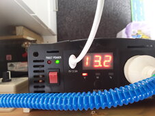
29.8 Pv ,battery is full ,13.6 to 14.4v TV on,phone charging,,inverter 13.3 to 14.4 no shut down yet in full sun but inverter sure working, no heat just fan cant make its mind up depending on incoming voltage,,,must need some sunblock rubbed in
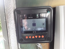
About the 28th thing is that info stored in the MT under Failure Info,I did look but nothing in there.
Keeping a close eye in things ,at least now I'm trusting this to a point but still need better inverter and still looking,can buy 1 anytime but top $$
Still waiting for other stuff arrive so not buying nothing at the moment till stupid xmas rubbish is gone,,
Thanks again much appreciated guys
Burst of sun just made inverter hit 14.9v and 14.7 ,I might shut it down, sure that's gone past preset range just when I said I trust it.not liking the bursts of power to the inverter when sun comes from behind cloud,,shouldn't it be nice and not a spike of energy or is that normal,

Ok Inverter HV alert beeped and turned off TV so I turned system off till I work things out,,nothing got hot just alarm and shut down but everything is now off
Really need inverter, awsome cloudy days but full sun something cant handle it especially the bursts from sun
 
Last edited:
You really need to get that charging voltage turned down. If it's set at 14.4 and you're getting 14.6, set for 14.0 and compensate manually.

14.7 is way too high for a car battery.
Yip ok ,trying now,got over voltage down to 15.1 from 15.5,,charge limit wont save at 14 so I go through the settings again to check them
Boggles my mind if 12v battery has all these higher presets in SEALED battery defaults
To be honest I'm about to give up and just leave it off,set up seems easy but my comprehension of how it all works is getting out of my league, I just wanted a simple safe set up , it's now goin bit awall on me because dont know what I need to do ,try program this thing or just get a inverter or just turn it off, lost trust in this set up..off to the deep thinking corner
Thanks
 
Last edited:
Don't give up! You've learned so much already, you're just at the fine tuning stage of things.

Sometime in the future you're going to want to play with solar again and you'll be digging into the minutia of systems because you've already dobe so much.

I think at this point you're getting hosed by terminology more than anything else. When a battery says "sealed" that could mean "we glued the caps on" to " our lawers don't trust you" which 99.99% of car batteries are. What you have is a flooded lead acid battery (FLA) that the company doesn't want you getting into the acid section of, so they throw a stickrr on it that says "Sealed" and tell you to pound sand if you open it up and hurt yourself.

That's why I've been pointing you at 13.8v for your charging, to keep it low enough to not set off the inverter and to get the controllr to behave with a battery that isn't what it says on the label.

Sadly, marketing is NOT your friend right now. With all the high voltage spikes you may even be low on water which is going to mess with things even more and NOT help get things stabilized.

This is another example of why I keep wanting to make a Marketing to English dictionary.
 
Last edited:
Yip ok ,trying now,got over voltage down to 15.1 from 15.5,,charge limit wont save at 14 so I go through the settings again to check them
Boggles my mind if 12v battery has all these higher presets in SEALED battery defaults
To be honest I'm about to give up and just leave it off,set up seems easy but my comprehension of how it all works is getting out of my league, I just wanted a simple safe set up , it's now goin bit awall on me because dont know what I need to do ,try program this thing or just get a inverter or just turn it off, lost trust in this set up..off to the deep thinking corner
Thanks
Don't give up, we're nearly there!
Page 18 of your manual tells you what depends on what. I'll try to attach a copy so everyone can see too.
I think there may be other "this-depends-on-that-setting" too, that are not in the manual.
Let me know what your Equalize charging voltage is set to - if this is still 14.6, reduce this to 14.4 and see if that lets you reduce the charging limit voltage to 14.4 - if so, this tells us that those two have to go down together.

Mods/experienced users: what are the rules on posting contact details for good deals on parts? I know of someone in his area who is very fair, very helpful, but is a commercial company, and i'm not sure if this is considered marketing (which i understand would be very frowned upon, lest it turns the forum into a advertising-fest)
 
Mods/experienced users: what are the rules on posting contact details for good deals on parts? I know of someone in his area who is very fair, very helpful, but is a commercial company, and i'm not sure if this is considered marketing (which i understand would be very frowned upon, lest it turns the forum into a advertising-fest)
There's an entire sub forum for online deals, you could post something in there.
 
14.7 is way too high for a car battery.
A car battery in a car is fine to 14.4 or 14.6 tops because the alternator hits it like that.
Yip ok ,trying now,got over voltage down to 15.1 from 15.5,,charge limit wont save at 14 so I go through the settings again to check them
What ‘I’ would do is go drastically “safe” - set float at 13V, boost reconnect at 12.8, Equalize to 14V, high voltage disconnect to 14.6, charging limit to 14V and see if that stabilizes. Then over following days decide about whether to leave it there or creep the settings up.
When a battery says "sealed" that could mean "we glued the caps on" to " our lawers don't trust you" which 99.99% of car batteries are. What you have is a flooded lead acid battery (FLA) that the company doesn't want you getting into the acid section of, so they throw a stickrr on it that says "Sealed" and tell you to pound sand if you open it up and hurt yourself
There’s actually a surprising but still smallish number of cars- I think BMW, VW, some Hondas? - can’t recall- that have AGMs from the factory these days.
 
Thanks, I had another go at settings but need the ok before I turn solar on

Over voltage disconnect voltage 14.1v
Charging limit voltage 13.5v
Over voltage reconnect 14v
Equalize charging voltage 13.3v
Boost charging voltage 13.0v
Float charging voltage 12.4v
Boost reconnect charging voltage 12.2
Low voltage reconnect 11.2v
Under voltage warning reconnect 12.1v
Under voltage warning 12v
Low voltage disconnect 11.1v
Discharging limit voltage 10.6v
Equalize duration 30min
Boost duration 30min
To me some settings still not seem correct and trying not to confuse myself

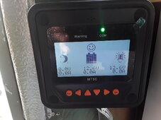
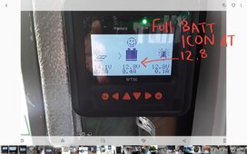
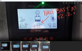
Also I add screenshot of battery icon at theses settings and shows it's full when before at 12+ volts showed about half battery so might have done something right lol,,,,,,,,,,,,,,,,,,,,,,,,,,,,,,,,,ok I see new post arrive before i send this one but this how i got it now and need opinion please
Thanks
20240102_173235.jpg
Just add its hard to find the correct method to change settings, yes I have the manual and its same as online one,and this took some time and hair went grey , I go back through soon and see if I Can get it better,
 
Last edited:
Just a screenshot and picture from now....pic from now show battery icon full at 12.6 to 12.8v,,,,,screenshot picture from yesterday's post shows battery icon at 12.2v under half charge so these settings done something good I hope,All powered up but out of sun for the day,,I would still like to get a bit lower and will attempt soon
Thanks again
Screenshot_20240102-193344_Gallery.jpgScreenshot_20240102-193205_Chrome.jpg
 
Was reading this before too and thanks to @mikefitz for a detailed explanation ,should sell that to them to put in the manual ?
This helps me so much understanding what these settings mean without confusion
Screenshot_20240102-203039_Chrome.jpg
 
Todays update
Well bugger me something worked
Bit of cloud but full sun , using power and battery sits on 13.3v and inverter holds on 13.2v full sun,no spikes of power,even the inverter fan now runs like it should, did get the charge limit to 13.5v . Makes my day if continues to work like this...the solar panel charging icon did stop showing the charge arrow and restart so presume that's the over voltage disconnect and reconnect working,,bit more fine tuning and it be sweet I hope
Just add when sun bursts from behind cloud inverter goes to 13.5 the back down immediately so that's awsome, been watching it for a while and seems ok,no warm wires,I'll get a proper DC breaker from hardware shop since couriers still not about

Thanks again for advice and help,
20240103_091740.jpg20240103_091632.jpg
Well it was good day,totally different than previous and now amazed nothing blew up ,,had TV and a 30w fan plugged into inverter with no effort.
Still looking at Boost charging and float charging because still bit high to what I have seen and with my settings
pretty happy with result now ,thanks again for guidance

9th Jan and still working sweet, ?
 
Last edited:
Things still good apart from the rain ,I been goin through settings ,mainly Boost,Float & Boost reconnect, Do they look ok ? This is where I'm having thinking trouble so asking for a check please ,not sure where to set them with how I have things,,,,system working ok
Thanks,,
Edit ok me put it back to where it was ! I guess this no good then

Over voltage disconnect voltage 14.1
Charging limit voltage 13.5
Over voltage reconnect 13.5
Equalize charging voltage 12.6
Boost charging voltage 12.6
Float charging voltage 12.6
Boost reconnect charging voltage 12.2
Low voltage reconnect 11.2
Under voltage warning reconnect 12.2
Under voltage warning 12
Low voltage disconnect 11.1
Discharging limit voltage 10.6
Equalize duration 30min
Boost duration 30min
 
Last edited:
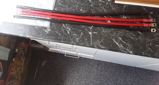
Well electrocute me,late courier order arrive of the 4awg arrive, makes the 5awg look small on the inverter, DC switches should be here today or in morning,just hope this cable not to fat for the DC switches, I did plan to have 2,just so all components can be turned off(mppt.inverter,) not that mppt needs one but gets hot in here when locked up so want nothing on.
Everything has been good but cant wait to install new stuff,gota sit on my hands,
I'll update with new pic when I do
Thanks again
 

Attachments

  • 20240110_124345.jpg
    20240110_124345.jpg
    384.2 KB · Views: 3
I do have question about the mppt controller load please......
Picture shows the current led light I'm using into mppt controller. 12v 72 LEDs but super bright so I use the 12v light dimmer with it.
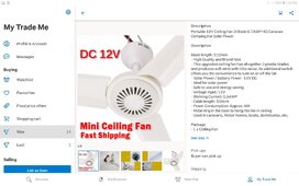
I brought this cheap fan that runs from solar or 12v battery..can I run both or can I conect these 2 into the same mppt controller load or does it need a separate conection to the battery and is there a max load for the mppt output,I see the mppt has load timer but that's it in that department.
This fan has alagater clips on ends for direct conection to battery.
Thanks
20240110_195402.jpgScreenshot_20240110-195303_Trade Me.jpg
Also I add picture of Google reply,,this fan is 0.7amps...mppt controller terminal output 12.7v on multimeter
20240110_203722.jpg
 
Last edited:
Well fun day,new 4awg on inverter, not sure what size goes to MPPT controller, I had 8awg in there before but only just got the 5awg wire in the terminal, 4 to big to fit there but dont know what should be there
got some decals to,but they AC instead of DC ,I look at those later,few things to tidy up here then next MISSION will be moving solar panel off the roof and have it hinged on back of caravan, Its been over hot here and it's like a heater on the roof ,its got air flow between but phew you can feel the inside ceiling hotter than other areas, apart from that it's working good and can turn off things now,battery, inverter & panel all have their own switch ??‍? .
20240111_201251.jpg
 
not sure what size goes to MPPT controller, I had 8awg in there before but only just got the 5awg wire in the terminal, 4 to big to fit there but dont know what should be there
That’s a 40A controller? At 12VDC nominal 8ga is good for 40A.
you can feel the inside ceiling hotter than other areas
usually that would be the other way around?
 
That’s a 40A controller? At 12VDC nominal 8ga is good for 40A.

usually that would be the other way around?
Thanks,controller just a 30amp,ok I put the 8 back in,hey isn't that downgrading ha,Me caravan a oldy style classic 1978 and has aluminum can grade roof,when its hot, it's hot,when cold it's cold,next to no insulation
Appreciate the info,thank you
 
caravan a oldy style classic 1978 and has aluminum can grade roof,when its hot, it's hot,when cold it's cold,next to no insulation
FWIW I do a ‘stationary’ RV. Saved me enough over a few years to buy a small piece of property.
I’m ‘stationary’ so I have a tiny yet substantial solar power system completely offgrid. I change stuff around for fun but need to finish employing all my solar. Currently just getting by on around 2kW of panels but the 2000W inverter is ample. Just pulled wire through my underground conduit today and hope to have another 1000W of panels online in the next week or so.

My RV is a 1976-ish Dutch Craft 25 that was built with a 4-season option, insulated floors, etc. so not “terrible” to heat. But I remodeled over time and added a lot of additional insulation- 1-1/2” foam to the ceilings, 1-1/2” to the walls, interior plexiglass ‘storm’ panels instead of window screens for winter. It’s comfortable and not expensive to heat.
But anyways, 1/4” plywood is ‘moderately priced’ and paints nicely. You can insulate yourself and improve your comfort and drop heating expenses tremendously, and use the plywood over that to create a clean, bright interior.
While 1.5” of foam doesn’t sound like much, the improvements cut my heating gallons by 1/3 last year, and this past summer’s work appears to be a substantial improvement as well but it’s hard to say how much at this point.
classic 1978 and has aluminum can grade roof,when its hot, it's hot,when cold it's cold,next to no insulation
I’m in Vermont. Winters are cold, my living space is warm.
Do a little at a time: at the prices of propane these days the winter fuel cost savings will be enough in just one season to be noticeable and “pay you back.” And my drains don’t even freeze anymore. 1976’s “4-season” camper was nothing like the insulation of a 2024 home, and now it is. I actually procured and need to install an air-to-air exchanger because it’s so ‘tight’ now- humidity is high and if I cook in the oven over 50-60 minutes the CO detector goes off this winter.

Just some encouragement but mostly food for thoughts.
 
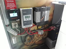
Hi @NZ12VOLT , your system is looking fantastic.
You have a well optimised layout with tidy wiring. The ASNZ code says that cabling has to be supported at least every 300mm (ie secured to the wall, in conduit, in cable trays, or some other method that prevents something pulling on the wires which might cause a terminal to come loose) and your system ticks that box.

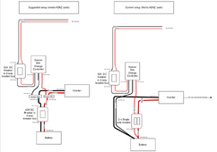
One thing that probably won't matter to you, but is important for other forum readers to note; the single pole DC breaker that sits between the Epever solar controller and the battery, and another single pole between the battery and the inverter, is not to ASNZ code. The code requires that both the positive and negative are broken by the breaker (ie a 2-pole breaker or isolator).
One way to achieve this with the breakers you have is to put in a pair of busbars. This means the breakers you have can go on the positive and negative and will disconnect the battery. The single pole breakers you have don't appear to be "ganged" (linked together so that both operate at the same time), which a proper 2-pole breaker would be.
You don't need a dedicated breaker for the inverter, and in a busbar layout the battery breaker does this job - ie it still cuts battery power to the inverter, plus you would usually have either a breaker or an isolator on the solar cabling, so that way you have a way to disconnect the inverter from all power sources, or to disconnect all power to the controller (ie for a 'reboot').

I've rattled up a diagram (its the same diagram, but in two formats; pdf and as an image ) to show this suggestion vs what the current layout is.
Cable weights are what would suit a 4-panel system with a 2000w inverter. Critique of the diagram is welcome;

Screenshot from 2024-01-21 20-29-02.png
 

Attachments

  • NZ12voltEpever.drawio.pdf
    36.6 KB · Views: 0
Also ... great to see he has used a label kit. This could save somebody a lot of head scratching, because although its all sooooooo obvious to everybody here, to somebody new to solar every box looks the same, and every wire looks the same gauge.
Its also a huge help when a user is at the other end of a phone and you are trying to talk them through rebooting the system, or putting a volt meter on various points to troubleshoot.
Well done NZ12Volt
 
Hi @NZ12VOLT , your system is looking fantastic.
You have a well optimised layout with tidy wiring. The ASNZ code says that cabling has to be supported at least every 300mm (ie secured to the wall, in conduit, in cable trays, or some other method that prevents something pulling on the wires which might cause a terminal to come loose) and your system ticks that box.

One thing that probably won't matter to you, but is important for other forum readers to note; the single pole DC breaker that sits between the Epever solar controller and the battery, and another single pole between the battery and the inverter, is not to ASNZ code. The code requires that both the positive and negative are broken by the breaker (ie a 2-pole breaker or isolator).
One way to achieve this with the breakers you have is to put in a pair of busbars. This means the breakers you have can go on the positive and negative and will disconnect the battery. The single pole breakers you have don't appear to be "ganged" (linked together so that both operate at the same time), which a proper 2-pole breaker would be.
You don't need a dedicated breaker for the inverter, and in a busbar layout the battery breaker does this job - ie it still cuts battery power to the inverter, plus you would usually have either a breaker or an isolator on the solar cabling, so that way you have a way to disconnect the inverter from all power sources, or to disconnect all power to the controller (ie for a 'reboot').

I've rattled up a diagram (its the same diagram, but in two formats; pdf and as an image ) to show this suggestion vs what the current layout is.
Cable weights are what would suit a 4-panel system with a 2000w inverter. Critique of the diagram is welcome;

View attachment 190362
Also ... great to see he has used a label kit. This could save somebody a lot of head scratching, because although its all sooooooo obvious to everybody here, to somebody new to solar every box looks the same, and every wire looks the same gauge.
Its also a huge help when a user is at the other end of a phone and you are trying to talk them through rebooting the system, or putting a volt meter on various points to troubleshoot.
Well done NZ12Volt
Sorry for late reply,have been reading here but not my own thread ha,
Yip basic label kit ,just handy for myself or if the old ticker stops someone knows what's going on with set up,
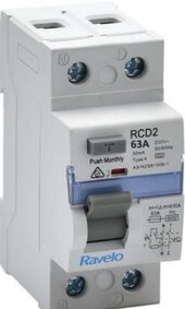
Excellent info on the charts for me thank you,as I reading I buy a twin pole breaker,Now its not spec but this brand 20240129_094320.jpg
Ravelo is in me price range ,same as other single pole ones I using,,others get up in price a bit and looking at busbars which probably get next week,they priced pretty high unless I get couple Burnsco cheap ones ,I could make some nice ones which I might do yet .
Everything has been working good, low cloudy days I just go main power ,not sure how to or if that can be overcome ,maybe another panel to increase amp input ,not sure yet on that
Appreciate the diagrams and will set up like that,Its clean and easy and safe,thanks
Best regards
Ian

Just add ok this one above I buy only 1 pole not 2 ,,oh another rookie error ,oh well in the spares box and get other
 
Last edited:
others get up in price a bit
Cheapo breakers might not work per industry standards. Don’t buy stuff on price, buy on function and value.

If a safety device is poorly made or designed and you burn everything down how much did you save?! Nothing. You lost everything.
 

diy solar

diy solar
Back
Top