diy solar

diy solar

Building the sickest ® VAWT ever. Brilliant minds unite please!!

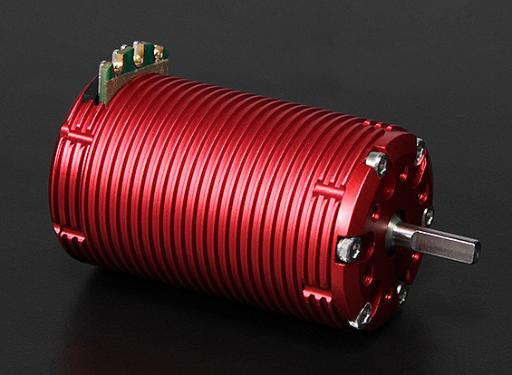
have considered a brushless electric motor as alternator? available from hobby store for rc car rc boat rc plane

1638386529080.jpeg

this one, a 2100KV (kilo rpm per volt metric) sensored brushless motor with max power rating 2000W


i’m using it to experiment with making a fan lol. so the inverse of what you’re doing.

but anyways, maybe a motor like this could be used in “regen” mode as the alternator?

it has three power conductors
and six sensor conductors

Poles: 4
Sensored: Yes (Standard 6 pin harness)
Max voltage: 15V (4S)
Max Current: 140A
Max Watts: 2100W
Resistance: 0.007ohm
Shaft Size: 5mm
Can Diameter: 42mm
Can Length: 70mm
Weight: 329g
 
Nah, My idea is to have an optimized airfoil cnc milled out of some kind of rubber. In that way it is easy to keep experimenting with straight or helix. It will take some welding skills on my part but one is never to old to learn
Coming back on this. Does anyone have a suggestion on what material I can use to have sheets of airfoil milled out of?

The idea is to have 2 halfs (the dotted line is the divider) of the airfoil profile like so
1638426702087.png
And then glue them to a stainless steel surface. They need to be bendable and easy to cut so I can experiment with different setups easily e.g. helix as well or only straight. This is a work in progress so please do not see the dimensions as something written in stone
 
sweet, I found something affordable. Do not know how to translate granulaatrubber. it's a rubber sheet made from smaller pieces or rubber
tl;dr is 2mx2mx2cm. I can glue together and have it milled somewhere

google translate to the rescue
 
Last edited:
grateful for these updates, excited for the teardrop airfoil ???or leaf??may the force of wind be with you!
 
Does one remember that old saying we all grew up with? That ancient wisdom one never knew the value of.

It goes something like this;

"why have only 48 poles if one can have 96 for double the price?"

Let's put this ancient wisdom to good use

1638437205653.png
please stop me if I am going over board. But I am going for the sickest ® alternator ever
 
Ahh never mind. What I will do is first wind one phase in a single strand manner and then do some output test at 60 rpm.
then I'll expand that single phase with another turn and test the output again. and again and again.

The 7mm holes allow for 24 wires at 1 mm to go through so that means about 177 meter of copper wire per phase.

Did I mention before this is going to be a brutal ® alternator anyone?
 
Does one remember that old saying we all grew up with? That ancient wisdom one never knew the value of.

It goes something like this;

"why have only 48 poles if one can have 96 for double the price?"

Let's put this ancient wisdom to good use


please stop me if I am going over board. But I am going for the sickest ® alternator ever

Magnetic field only does good when it passes through windings. Cores serve to channel field through windings, and air gaps are a necessary evil to allow mechanical motion.

I saw a lay-up you had with magnets on OSB (yuck!) or similar material. Are the magnets supposed to interact with core and windings near one face only? If so, I suggest pole pieces to duct the field around back from one magnet to the next. Otherwise, "resistance" of that long path through air (or OSB, 3-D printed plastic, etc.) will greatly drop the field strength in windings.

We've got some devices that look like the stator of a motor, basically an "E" shaped core (more than 3 legs) rolled into a circle. Windings between the legs drive magnetic field, the backbone links the legs, and the legs present the magnetic field lines to "whatever" is between them (not an armature in our case.)

Also at work, we're messing around with containing magnetic fields. Have a switch-mode power supply in a rack next to analog boards. Putting a shield of Mu-metal against one face of the SMPS results in stronger magnetic field where the PCB is located. We're planning to make Mu-metal enclosures which trap magnetic field but allow cooling air flow.

You can get meters that measure multiple Tesla with a skinny probe, probably good for measuring between parts of a motor/alternator. Also clamp meters (some with flexible "rope" rather than clamp), up into the 1000's of amps or down to uA. In your case you're not going to care about microamps of eddy currents, but we do.

So given NO one is objecting to the 96 pole variant I am assuming that is something to try indeed. @sunshine_eggo yes assumptions again but how else to proceed?

My suggestion was decide whether you want to play with alternators or with airfoils and concentrate on that while using off-the-shelf solution for other. Actually for alternator development, use motor drive rather than wind turbine.

Once you've figured out both, built your working scale model or full size system.

This shows that we'll need a bigger badder foil, a sail, as @Hedges calls it, of sorts

And when I said "Sail", I meant that in a bad way. How much force it will apply to your roof (or other mounting structure) during high winds.
 
Magnetic field only does good when it passes through windings. Cores serve to channel field through windings, and air gaps are a necessary evil to allow mechanical motion.
sure it does, unless I am missing the finer points I am assuming this was meant as a refresher for the new comers to the topic?
 
I suggest pole pieces to duct the field around back from one magnet to the next. Otherwise, "resistance" of that long path through air (or OSB, 3-D printed plastic, etc.) will greatly drop the field strength in windings.
can you please rephrase? i am confused a bit.
 
Back
Top