diy solar

diy solar

Let's melt some alternators

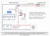
In the Nordkyn series, he references something similar to what is being described here (leaving a starter battery in place to help with load absorption). This is outlined in the image below:
Screen Shot 2020-05-20 at 9.56.07 AM.png

I have two questions:
1. Coming off the LFP bank, the BMS has a control cable going to what, is that simply a fuse (not sure if that symbol represents fuse or relay)?
2. How is the BMS Control cable interacting with a fuse?
 
It looks like it could be a contactor or relay. The settings in the BMS would monitor the cell voltage, and when reaching the configuration of the HVC, it would open the relay preventing any more charge. The alternator would continue to charge the SLA and it would absorb the load spike from disconnecting the LFP batteries. I plan to use and ARGO FET and a Victron battery protect to manage the alternator charging.
 
It looks like it could be a contactor or relay. The settings in the BMS would monitor the cell voltage, and when reaching the configuration of the HVC, it would open the relay preventing any more charge. The alternator would continue to charge the SLA and it would absorb the load spike from disconnecting the LFP batteries. I plan to use and ARGO FET and a Victron battery protect to manage the alternator charging.

Thanks, I guess the blue cylinder in the pos feed from the LFP represents the fuse. Wouldn't that relay need to be normally closed so that the LFP is online and feeding the load bus? What BMS has a control cable that could talk to a contactor or relay that would cause it to move from normally closed to normally open in the event of an HVC?
 
My set up will be 16 x 280ah LFP from XUBA. Ill control them in a 4P4S config using a REC-BMS. This BMS has CAN-BUS out that plugs directly into a Victron GX device, and inherently controls all the rest of my Vicron gear on the boat. Its a complex system, but there is redundancy on each charging and discharge outlet so i dont fry the batteries.
 
I have a flooded start battery and a LFP house battery. They are connected through a relay when voltage exeeds 13.4v. I am working on the theory that if a get an HVD the start battery will absorb the spike and save the alternator. I have read both pros and cons on this approach. But I also Figure I’ll keep my charge output under 14.1v so I won’t reach HVD and treat my batteries better.
Ding !
Ding !
Ding!
We have a winner
 
Back
Top