diy solar

diy solar

Loads and battery on common DC bus from SCC.

Mattb4

Solar Wizard
Joined
Jul 15, 2022
Messages
4,009
Location
NW AR
Perhaps someone can help explain the interaction of battery charge and load supply when operating off a common DC bus for operation of AIO/SCC. I know that if you are supplying the DC bus from the AIO at a certain amperage (created by the SCC raising bus potential) that loads and the battery will split that total based on load first and remainder going towards battery but I struggle putting into words for someone that might not understand it.

For instance you have a 12v SCC outputting 20 amps charge current to the common DC bus. The battery is the only load at the moment so it takes all of the amperage in. That amperage is created by the SCC forcing a higher potential on the DC bus to create current flow. You then turn on a load of 10 amps worth (1 amp on the 120v inverter). The amperage going to charge the battery drops to 10a. How to explain this is what I am looking to do.

Thanks for any clarity.
 
Warning: The following explanation is very simplified, perhaps overly so. However, it is a reasonable first approximation way of thinking of it.

The SCC, Battery and Load are all in parallel.

1669497056864.png

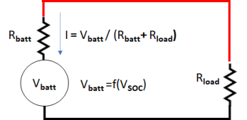
If the voltage of the SCC is greater than the battery, it will drive current into the battery. For this case, we can think of the battery as a resister with an effective resistance that is a complex factor of the battery SOC and the voltage being applied to it. As these variables change, the effective resistance will change. Increasing voltage at the terminals and increasing SOC will both cause the effective resistance to go up. (This is an extreme simplification, but it works for the purposes of this discussion.)


1669498892526.png

So, for a given voltage from the SCC, there will be Vscc/Rload going into the load and Vscc/Rbatt going into the battery. This model works for an given snapshot in time, but as you will see below, it does not work over a period of time because the Rbatt is not a constant.

Now lets imagine the Load increases. This would mean Rload goes down and the current going through it will go up. As long as the SCC can supply the extra current without affecting its voltage, the current into the battery will not change. If the SCC voltage starts to go down due to the load, the current into the load will go down in a linear fashion defined by Iload = Vscc/Rload. However, since the effective resistance of the battery changes with the voltage on the terminal, the lower voltage will actually result in a higher effective resistance through the battery. Consequently, the reduction in current to the battery is a non-linear function of the charge controller voltage. Consequently, the current through the battery will go down faster than the current through the load. This will continue till the SCC voltage = the battery voltage. At that point the effective resistance of the battery is infinite and all the current is going through the load.

1669498627970.png


Continuing the thought exercise, let's go back to when the current is flowing into both the load and battery. Over time, the SOC of the battery will go up, causing the effective resistance to go up as well so the current into the battery will go down. Eventually, the SOC reaches 100%, the effective resistance of the battery will again be infinite and the current into the battery will go to zero. However, the SCC can still be providing current to the load.

Meanwhile, this is all complicated by the fact that the SCC is not a linear device either. In its bulk mode, it will pump as much current into the system as it can. During this time, it will make the voltage as high as it can up to the preset charge voltage. Once the system hits the preset charge voltage, the SCC will hold that voltage by reducing its output current. As the battery charges up, it will take less and less current till the SCC is only supplying enough current to drive the load at the preset voltage.


I hope this helps. I tried to simplify the concepts but when I read back over it I am not sure I accomplished the goal
 
I an not happy with the equivalent circuit of the battery and the calculation for the current flowing into the battery. The battery has an internal voltage source and ideally this should be taken into account.
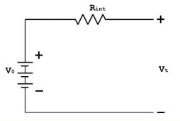
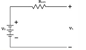
The very simple model of the battery is,
battery circuit.jpg
Thus the current into the battery is: (solar charger voltage - battery internal voltage ) / battery internal resistance.

effective resistance of the battery changes with the voltage on the terminal, the lower voltage will actually result in a higher effective resistance through the battery
The current reduces basically because there is a smaller difference between the internal battery voltage generator and the solar charger, the battery internal resistance in the simplified equivalent diagram stays the same.
This will continue till the SCC voltage = the battery voltage. At that point the effective resistance of the battery is infinite and all the current is going through the load.
The battery resistance stays at the normal and at almost constant value, current stops flowing because the battery internal voltage source ( that increases with SOC), equals the charge voltage.

In the proposed simple circuit where the battery is only a resistor, the concept fails when the solar charger is not producing current. Under this condition the battery should supply the load and thus needs to contain a voltage source.

Mike
 
Last edited:
Perhaps someone can help explain the interaction of battery charge and load supply when operating off a common DC bus for operation of AIO/SCC. I know that if you are supplying the DC bus from the AIO at a certain amperage (created by the SCC raising bus potential) that loads and the battery will split that total based on load first and remainder going towards battery but I struggle putting into words for someone that might not understand it.

For instance you have a 12v SCC outputting 20 amps charge current to the common DC bus. The battery is the only load at the moment so it takes all of the amperage in. That amperage is created by the SCC forcing a higher potential on the DC bus to create current flow. You then turn on a load of 10 amps worth (1 amp on the 120v inverter). The amperage going to charge the battery drops to 10a. How to explain this is what I am looking to do.

Thanks for any clarity.
All done by battery charge voltage regulation.

The inverter load may cause SCC to trip into a new full battery absorb charge cycle which could be hard on battery. Many SCC controllers limit the number of times per day a full absorb charge cycle is allowed to happen. Alternate method which is similar is the SCC charge controller has a timer that prevents multiple full absorb charge cycles to occur within the timer interval.

As long as SCC only tries to maintain float voltage it can still deliver full available PV power and prevent going into a full absorb charge cycle.

The other issue that can happen when a full absorb cycle is under way is the inverter draw screws up the absorb timer or absorb battery current taper termination. This is why SCC's almost always rely on timed absorb and not current taper off to terminate absorb cycle, and freezes absorb timer countdown whenever battery voltage drops below absorb voltage due to an inverter load.
 
Last edited:
Current flows from a higher voltage source to a lower voltage source/or load. (Load being a zero voltage source)
 
I an not happy with the equivalent circuit of the battery and the calculation for the current flowing into the battery. The battery has an internal voltage source and ideally this should be taken into account.
The very simple model of the battery is,
View attachment 121941
Thus the current into the battery is: (solar charger voltage - battery internal voltage ) / battery internal resistance.


The current reduces basically because there is a smaller difference between the internal battery voltage generator and the solar charger, the battery internal resistance in the simplified equivalent diagram stays the same.

The battery resistance stays at the normal and at almost constant value, current stops flowing because the battery internal voltage source ( that increases with SOC), equals the charge voltage.

In the proposed simple circuit where the battery is only a resistor, the concept fails when the solar charger is not producing current. Under this condition the battery should supply the load and thus needs to contain a voltage source.

Mike
All true. As I said in the post, it is a gross simplification. I was trying to come up with a simple way of explaining how the current from the SCC gets distributed. I was trying to avoid the complication of modeling the voltage supply of the battery by using the concept of effective resistance that will vary with the SOC. Perhaps I tried to simplify it too much.


BTW: If we want to get into the weeds on a simulation of the system, even this model is a simplification:

1669516028312.png

The internal battery voltage is not a constant, as a first approximation, it is a function of SOC.... but even that is not completely correct.

Meanwhile the SCC would have to be modeled with a Diode in front of it. (It won't sync current). Furthermore, it has a current mode with a max current and constant voltage mode where it limits the current. Consequently, there are all sorts of discontinuities in behavior depending on what power is coming in and what state it thinks the battery is in.
 
All true. As I said in the post, it is a gross simplification. I was trying to come up with a simple way of explaining how the current from the SCC gets distributed. I was trying to avoid the complication of modeling the voltage supply of the battery by using the concept of effective resistance that will vary with the SOC. Perhaps I tried to simplify it too much.


...
I do not believe you are oversimplifying since it was what I was asking for. However the concept of using resistance to explain the operation might be a bit too technical. BTW, I appreciate all the thought and effort you put into your responses.

Perhaps as Timselectric post puts forth the voltage explanation provides a easier definition. Keeping in mind that when connected to a common bus all items are seeing the same voltage. But in order for current to flow the potential of the supply must be higher than the item being powered. Regular loads offer zero potential therefore they are going to take up current at the highest rate. A battery can only take up current based on the difference in the supply potential and its internal voltage.

So as loads are applied to the DC common bus the SCC acts to raise voltage based on the ability of the solar panels to provide it. As load starts to exceed supply from the panels the voltage drops down to the point that the batteries internal voltage becomes higher than the supply and now it begins to flow current.
 
All done by battery charge voltage regulation.

The inverter load may cause SCC to trip into a new full battery absorb charge cycle which could be hard on battery. Many SCC controllers limit the number of times per day a full absorb charge cycle is allowed to happen. Alternate method which is similar is the SCC charge controller has a timer that prevents multiple full absorb charge cycles to occur within the timer interval.

As long as SCC only tries to maintain float voltage it can still deliver full available PV power and prevent going into a full absorb charge cycle.

The other issue that can happen when a full absorb cycle is under way is the inverter draw screws up the absorb timer or absorb battery current taper termination. This is why SCC's almost always rely on timed absorb and not current taper off to terminate absorb cycle, and freezes absorb timer countdown whenever battery voltage drops below absorb voltage due to an inverter load.
Thanks for your explanation of the battery charging considerations of the SCC and the interaction with load supply. A lot of the programed settings on these devices are not made available to the end user. This complicates things when there is different use cases.
 
I do not believe you are oversimplifying since it was what I was asking for. However the concept of using resistance to explain the operation might be a bit too technical. BTW, I appreciate all the thought and effort you put into your responses.

Perhaps as Timselectric post puts forth the voltage explanation provides a easier definition. Keeping in mind that when connected to a common bus all items are seeing the same voltage. But in order for current to flow the potential of the supply must be higher than the item being powered. Regular loads offer zero potential therefore they are going to take up current at the highest rate. A battery can only take up current based on the difference in the supply potential and its internal voltage.

Not true once the terminal voltage is more positive then the battery voltage current flow as a function of equivalent resistance which is a function of chemistry. In the case of lithium a small difference in voltage can result in big currents flowing. In many cases the lithium can be viewed as a simple load in charge mode no different to any other load.

The actual difference in supply potential versus internal potential has little to do with it. Very large currents can flow across all potential differences
So as loads are applied to the DC common bus the SCC acts to raise voltage based on the ability of the solar panels to provide it. As load starts to exceed supply from the panels the voltage drops down to the point that the batteries internal voltage becomes higher than the supply and now it begins to flow current.
 
I do not believe you are oversimplifying since it was what I was asking for. However the concept of using resistance to explain the operation might be a bit too technical. BTW, I appreciate all the thought and effort you put into your responses.

Perhaps as Timselectric post puts forth the voltage explanation provides a easier definition. Keeping in mind that when connected to a common bus all items are seeing the same voltage. But in order for current to flow the potential of the supply must be higher than the item being powered. Regular loads offer zero potential therefore they are going to take up current at the highest rate. A battery can only take up current based on the difference in the supply potential and its internal voltage.

So as loads are applied to the DC common bus the SCC acts to raise voltage based on the ability of the solar panels to provide it. As load starts to exceed supply from the panels the voltage drops down to the point that the batteries internal voltage becomes higher than the supply and now it begins to flow current.
As more solar power is available then an DCc assuming the load can take it will automatically supply more current. It doesn’t necessarily need to raise volyage to do that as typically battery resistance is so low that simply more current can be delivered anyway. Without any need to raise terminal voltage. This is all taken care off in the regulator in the solar controller
 
Current will not flow into a battery unless the external voltage is higher than the voltage of the battery.
If the bus bar voltage is higher than the battery voltage, Current flows into the battery. If the bus bar voltage is lower than the battery, Current flows out of the battery.
That's as simple as it gets.
My previous post just said it in less words.

Resistance only controls the speed at which current can flow.
Voltage will always equalize between parallel connections.
I was agreeing with your previous post. Sorry if you got the impression I was not.
 
I copy this from sciencedirect ,

4.3.4.1.3 Solar Charge Controller​

A solar charge controller is used to keep the battery from overcharging by regulating the voltage and current coming from the solar panel to the battery. It is programmed at 15-A/200-W unit and uses MPPT (maximum power point tracking) to accelerate solar charging of the battery up to 30% per day. MPPT checks the output of the solar panel compares it to the battery voltage and adjusts it to the best voltage in order to get maximum current in to the battery
 
OK. So I oversimplified.

If we put it all together, you could model the system like this.


1669582709534.png

This diagram is still deceptively simple looking because Vbatt is a complex function of the SOC. In addition, the function for Vscc is particularly complicated because the function changes completely when it transitions from bulk to accumulation and again when it transitions from accumulation to float.

Furthermore, with the diode function at the SCC, the model changes to something like this if Vscc gets below the battery terminal voltage

1669581593587.png

Even with all of my caveats, there are subtleties that are not accounted for. As an example, The battery voltage is not a strict function of SOC. When the SCC goes into float mode, the battery voltage will drift down to it's resting voltage (or the SCC float voltage) without a significant change in SOC.
 
Back
Top