You are using an out of date browser. It may not display this or other websites correctly.
You should upgrade or use an alternative browser.
You should upgrade or use an alternative browser.
MPPT Battery Charging - AC component during high PV loads
- Thread starter CMDRZOD
- Start date
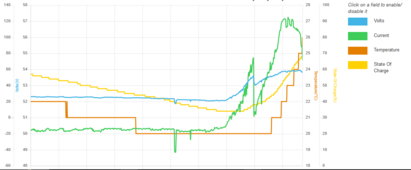
I mainly see temp trac SOC, is that AC current or charge current?View attachment 201295
Graph from this morning. Temperature didnt start to rise until the loads started, you can see where the first two ramp up through the current bar.
CMDRZOD
New Member
So remove current from the graph? This graph is only showing battery data. This data is not for the output side, besides seeing the battery current drop as loads start.
Battery ripple current becomes problem when it starts to heat up the batteries and that appears to be the situation OP has.AC ripple is normal and does not really have any impact on the battery cycle time as its is a faction of the voltage range of what is considered one cycle ( 100 to 0 SOC ) so there is no need to add parts
For added capacitors, you may not realize that your four Conext MPPT 100 have significant capacitor banks on the output already as they are design to work with lead-acid, which from a ripple perspective do less than Lifepo4 for ripple suppression
So spend that $$ and add batteries, the super capacitor will provided no improvements to your system.
Disclaimer: I was part of the team at Xantrex that designed the hardware you are using
0.1C ripple would be ok and 10C ripple would be disaster for most batteries. Between that "it depends"
Lifepo4 will also experience considerably higher ripple current than lead-acid as it has lower internal resistance than the lead.
Internal capacitors could be borderline insufficient when there is extremely low impedance Lifepo4 connected to the inverter.
My guess is that 6848 Pro doesn't have enough input capacitance to filter out the 120hz ripple. Feel free to comment on how much capacitance there is in the input if you got insight on the design.
Plenty of research material available on topic:
ahem ahem.. sci-hub might have something something on paywalled scientific articles.
ahem ahem.. sci-hub might have something something on paywalled scientific articles.
Did a quick LTSpice run on what might be going on:
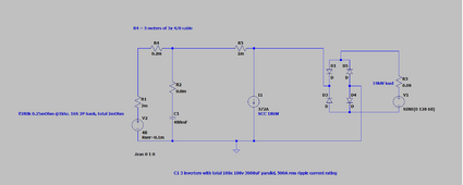
Not sure how close I guessed the input filtering capacitance on Conext inverters and it is a bit of quesswork here and there but shows easily why you see the ripple current.
In above simulation battery will experience 203A rms ripple current and C1(inverter filtering) will handle only 160A rms.

Not sure how close I guessed the input filtering capacitance on Conext inverters and it is a bit of quesswork here and there but shows easily why you see the ripple current.
In above simulation battery will experience 203A rms ripple current and C1(inverter filtering) will handle only 160A rms.
btw: OP's measured 300A rms to questimated 2 milliohm battery internal impedance is 180W internal losses in the battery.
No wonder if it likes to heat up.
Crazy as it may sound but improving the battery cooling might be one option if the damage mechanism is mostly heat-related!
No wonder if it likes to heat up.
Crazy as it may sound but improving the battery cooling might be one option if the damage mechanism is mostly heat-related!
Supercapacitor you are looking at has 6 milliohm internal impedance so it won't do much anything when parallel with a battery bank that has (guestimated) 2 milliohm internal impedance. You would need some choke between the battery and the supercapacitor bank.Hi there. I'm looking at an eaton 130 farad capacitor, rated for 62V part no XLM-62R1137A-R. The heating doesn't appear to be much, the highest reported temperature I've seen from the BMS is 34C which I don't believe is terrible, but not ideal. My goal is to keep battery temperature below 30C.
I believe this ripple, while not catastrophic, is detrimental to battery temperature and life.
Edit: 10 turn 300mm diameter air-core inductor would fix the ripple issue totally at least in the Spice-simulation above. Downside is that you need 30 meters of 4/0 cable for that.
Last edited:
Looking bit further you don't actually need any supercapacitors. Just find a scrap pile with 3 microwaves. Rip out the transformers, separate the core halves (need 2 minutes with angle grinder on the weld) and insert 10 turns(or as much as you can) of 4/0 cable in the transformer core. Insert 1 mm glasssfiber/cardboard shims between the core halves and clamp them together. Now you have three 100uH chokes. Combined in parallel they should handle way over 400A before saturating or overheating.Supercapacitor you are looking at has 6 milliohm internal impedance so it won't do much anything when parallel with a battery bank that has (guestimated) 2 milliohm internal impedance. You would need some choke between the battery and the supercapacitor bank.
CMDRZOD
New Member
Incredible MattFin. Might be going dump diving this summer I suppose. I have many large ballasts for outdoor lights here, I wonder if those cores would work. Theyre not the oil filled type so the transformer is easy to get at. Thank you for your thoughts on this.
wpns
Solar Joules are catch and release
Which has ~5 mohm resistance.you need 30 meters of 4/0 cable
If the ballasts are something like over 8lbs each they should have enough large cores. You can use https://www.calculators.live/gapped-core-inductance to calculate the inductance and saturation amps. Most silicon steel cores should handle at least 15 000 gauss before saturating so aim for under 100 gauss/A for a 150A choke.Incredible MattFin. Might be going dump diving this summer I suppose. I have many large ballasts for outdoor lights here, I wonder if those cores would work. Theyre not the oil filled type so the transformer is easy to get at. Thank you for your thoughts on this.
Need only 10 meters of cable for the air-core inductor mentioned but assumed that it needs to be 3x 4/0 parallel, making it 30 meters total price-wise. Thus only ~0.5mOhm resistance.Which has ~5 mohm resistance.
Solar Guppy
Red Cobra Guppy
Battery ripple current becomes problem when it starts to heat up the batteries and that appears to be the situation OP ...
Ripple is a very small part of the losses, most if it is just IR losses ( current - resistance )
Nothing needs to be added for the XW, its well designed and decades of proven performance
CMDRZOD
New Member
Got the capacitor installed. Was hesitant to charge it, finally settled on using a battery charger. Worked a treat and in 20 minutes the capacitor was charged and ready.
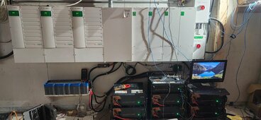
This is a new install. Still have some cleanup and finalization to do.
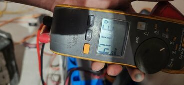
AC amp reading taken ahead of capacitor.
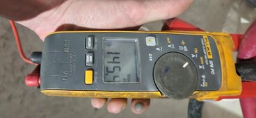
AC Amp reading after capacitor on battery leads
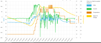
My first full day of good sun after installation. You can see battery temperature has decreased by nearly 10C compared to the original images posted. This is still very early but so far I am quite happy with the results.
I'd like to find a better way to terminate cables at the capacitor. Was thinking an insulated terminal bar. Have the cap stem go through the terminal bar and 4/0 connect to individual terminals.

This is a new install. Still have some cleanup and finalization to do.

AC amp reading taken ahead of capacitor.

AC Amp reading after capacitor on battery leads

My first full day of good sun after installation. You can see battery temperature has decreased by nearly 10C compared to the original images posted. This is still very early but so far I am quite happy with the results.
I'd like to find a better way to terminate cables at the capacitor. Was thinking an insulated terminal bar. Have the cap stem go through the terminal bar and 4/0 connect to individual terminals.
wpns
Solar Joules are catch and release
Nice! I learned something today, thank you!
wheisenburg
Independent Solar Consultant
When I first started up my system, I had not changed the defaults for the charge current. I have only two inverters at 140 amps each, and they pushed 280 amps into the batteries when I started a charging cycle. The ensuing racket was quite alarming and I was pretty sure that my system was about to blow up in a spectacular explosion.I switch my fluke true RMS meter to AC amps, and it will read 270-300 amps AC at exactly 120hz.
Well nothing actually happened and I adjusted the charge current down to a sensible level like 60 amps total. I was able to determine that the cause was a panel cover on one of my wire channels carrying the dual 4/0 cables was vibrating. It did make me aware that the charge current is in no way a flat DC signal, at least as far as what is passing from the inverter/chargers to my main battery bus bars. It appears that it is something more like a rectified sine wave, so it makes sense that this would appear as a 120 HZ signal.
Ideally an inductor in series, and a capacitor in parallel would make a great low pass filter. Unfortunately, an inductor of sufficient size, capable of carrying 500 amps would probably cost more than my house and be the size of a utility transformer.
With batteries as the SOC rises the internal resistance of the batteries also rises. More internal resistance at the same current equals more heat. This is expected. It is why the charging cycle on a LFE battery starts off with a lot of current. Often they will hold the current constant at this point. This would be the "Bulk" phase of the charge. As the battery approaches full charge the charging cycle will change to absorption. During this phase they will hold the voltage constant. The current will gradually reduce until the charging cycle ends. Now this is what happens when you use the 2 phase charging cycle programmed into the inverter/charger. I don't know exactly how the DC charge controllers do their charge cycle.
Nice system by the way. The dual system I have is more than adequate for my house and is basically for back up only. It is AC coupled. I was worried about the agility to handle the current from my fairly large AC couple PV so I am building a "PV Shedding Controller" You can see this here:

Building a PV Shedding Controller for AC Coupled Solar
Back Ground I have an Enphase system with 35*350 watt panels. It uses the IQ8+ micro inverters at 295 watts each. So the total possible output is 10,325 watts. The actual maximum output is about 9000 watts. I have 7 panels that face east and 28 that face west. The slope of my roof is about...
Last edited:
wheisenburg
Independent Solar Consultant
Considering you are storing enough energy in there to power a small rail gun, you really need to make sure there is no chance you will ever short out your DC cables. I am careful around my DC cables anyway, but shorting these will be like a bomb going off. The rectangular metal boxes under my batteries contain 600 amp bus bars. Just underneath the busbar in the wire gutter, I have a pair of class T fuses. One for each 4/0 positive cable.I'd like to find a better way to terminate cables at the capacitor.
CMDRZOD
New Member
Yes. I was originally going to bolt the cap to the 3/4 plywood behind it vertically with the terminals mounted upwards but it seemed to be a hazard in case anything fell down to the cap terminals. Instead I decided this small shelf would be the best way of mounting.Considering you are storing enough energy in there to power a small rail gun, you really need to make sure there is no chance you will ever short out your DC cables. I am careful around my DC cables anyway, but shorting these will be like a bomb going off. The rectangular metal boxes under my batteries contain 600 amp bus bars. Just underneath the busbar in the wire gutter, I have a pair of class T fuses. One for each 4/0 positive cable.
I am very aware of the hazard this capacitor presents and will find a solution to safely terminate the cables while insulating the terminal connections.
Was thinking an insulated terminal block that I could drill out the capacitor stem to go through the terminal block and have a nut to keep it tight.
Similar threads
- Replies
- 5
- Views
- 176
- Replies
- 11
- Views
- 427
- Replies
- 60
- Views
- 2K
- Replies
- 39
- Views
- 1K


