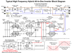
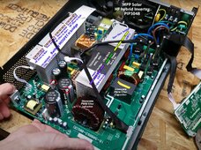
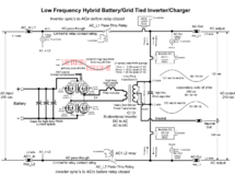
Drawing was reverse engineered by Ukrainian guy from what looks like Chinese clone of Voltronic design (EPEver, Must, etc.)and it's very European. America exists too.
Last edited:
Drawing was reverse engineered by Ukrainian guy from what looks like Chinese clone of Voltronic design (EPEver, Must, etc.)and it's very European. America exists too.
That's not the isolation being referred to.
You have to understand the Victron rs450 has isolation features that are different from its 250/150V smart/blue solar sccs.
That referenced thread means nothing.
View attachment 182737View attachment 182738View attachment 182739
Drawing was revere engineered by Ukrainian guy from what looks like Chinese clone of Voltronic design (EPEver, Must, etc.)
I didn't find the thread with a quick search either.
Likely scenario. FETs fail, often shorted.
The "isolation" I'm referring to is galvanic isolation between SCC PV+ input and battery+ output.
Basic architecture is buck converter, a FET and an inductor connecting those, plus a freewheel diode. Not galvanically isolated.
The other architecture uses transformer isolation for PV+. Even if PV- is hard wired to battery-. That I think keeps battery safe from this failure mode.
The manual for my SIC-40 addresses this risk, and calls for a disconnect mechanism. After much discussion, came to the realization that PV breaker can do it, needs remote trip mechanism.
A different approach would be crowbar PV. But that would present a drain or short to battery, given that SCC was bad. So I plan to use remote trip breaker.
I was a bit unprecise with my question. You've mentioned "Battery is inherently isolated due to HF step up transformer unless batt- and PV- are tied together internally". Do you know if the batt- and PV- are tied together inside the EG4-6500EX?They have to have them otherwise how else can they step up 48V to 200 - 400Vdc for the HVDC bus?
It probably has buck-boost MPPT converters since spec sheet states 90VDC - 450VDC MPPT range. Internal inverter DC bus voltage is likely 200Vdc.
Oh yes, forgot that Solark is split phase. Could be achieved by combining two 120V inverters side by side fed from center tapped HF transformer producing +/-200Vdc.and maybe needing two different pictures depending on how the split-phase is achieved.
No idea, never seen inside of one before.Do you know if the batt- and PV- are tied together inside the EG4-6500EX?
I'm not certain it needs remote trip.
Another variable is how air gapped the AC in and AC out can be, and whether there are more internal CTs to help with higher end features. Like generator/grid assist and AC coupling. Some of those don’t matter for this thread but would matter for other discussionsOh yes, forgot that Solark is split phase. Could be achieved by combining two 120V inverters side by side fed from center tapped HF transformer producing +/-200Vdc.
Very interesting schema to better understand what's going on!This is typical AIO high voltage PV input inverter topology. Solark probably is the same. @Solar Guppy can you confirm?
Then how would Victron trip for an event to shut down PV?If breaker is to serve as an isolator between PV panel and battery, something has to trip it. It won't be current, not enough. Therefore, some remote trip, whether a solenoid or a ganged 1A breaker with > 5A fed through it.
OK, I will open and disconnect all wires on one of my EG4-6500EX and will do a resistance measurement between batt- and PV1/2- to be really sure if they are isolated or not. I would sleep better if I know that a failed FED would not be able to destroy all BMS's and battery cells!No idea, never seen inside of one before.
Yes. The inverter has to synchronize to grid waveform in order to inject solar into AC loads with grid assist. The hardware to grid export is there but this feature is not enabled probably due to lack of software support or extra hardware required to comply with anti-islanding, I am not sure.and it could also be used as a grid-tied inverter and feed energy back to the grid (if the firmware/controller of the AIO allows this working mode)? From the schema it looks like that this may be possible?!
Then how would Victron trip for an event to shut down PV?
From the theory point of view an off-grid inverter is a voltage source which generates it's AC output frequency by itself (via PWM) and a grid-tied inverter is a current source which must follow the grid waveform (by pushing current into the grid by trying to raise the voltage a bit over the grid voltage). It's interesting, that just with a different PWM modulation and different controlling of the PWM sinewave H-bridge, both scenarios could be achieved with just one circuit.Yes. The inverter has to synchronize to grid waveform in order to inject solar into AC loads with grid assist. The hardware to grid export is there but this feature is not enabled probably due to lack of software support or extra hardware required to comply with anti-islanding, I am not sure.
grid-tied inverter is a current source which must follow the grid waveform (by pushing current into the grid by trying to raise the voltage a bit over the grid voltage).
Not to be a d*ck, but watts an milliamps are two different but related things.and noise
There's a lot of differences people glance over.. Self consumption of the EG4 is 25W compared to 15mA on the Victron. That's quite a bit of heat/inefficiency difference. Victron is also fully isolated.. along with other differences.. so you do in fact get a higher quality product so it isn't exactly a 1 to 1 comparison solely on price... whether those differences matter to you is up to you.
Actually it is my created diagram. It is a generic HF AIO inverter. It is cheapest models with no isolation to PV charge controller.Drawing was reverse engineered by Ukrainian guy from what looks like Chinese clone of Voltronic design (EPEver, Must, etc.)


The inverter AC side PWM transistors are the AC input synchronous rectifiers from AC input to supply HV DC to be used by battery to HVDC converter to charge batteries.Can the PWM transistors be used to disconnect high voltage bus from the grid AC to allow charging when on grid?


