Zwy
Emperor Of Solar
I did not see Victron contest the answer."Accepted answer" i.e. not authoritative.
It doesn't address at all the issue of whether the MPPT charger will "fail safe" or "fail deadly".


I did not see Victron contest the answer."Accepted answer" i.e. not authoritative.
It doesn't address at all the issue of whether the MPPT charger will "fail safe" or "fail deadly".
It's Victron's site, they could easily address the question and answer if it was incorrect or remove the post."Silence does not imply consent"
(at least that has become a popular claim recently)
Maybe giving a more detailed explanation would not help their sales.
For Midnight, it would.
Is the EG4 FET based? You are making ass umptions.OK, we'll assume (the safer assumption) it is not isolated in any way, and if FETs fail shorted it will connect PV+ to output. When BMS opens, BMS FETs will fail, shorting PV+ to cells, which will overcharge, bloat, vent.
"Got a light?"
Victron has fans too.
EG4 consumes nothing when it isn't running. I'll wager the Victron does not shut down when PV input drops to 0 as it runs communication which will draw power. The EG4 does shut down.
If you're concerned about it taking 25W when running with 5000W PV input, you have some serious issues.
With the fans running on the Victron, what is the self consumption? I can assure you it isn't 15mA.
The 2 Victron MPPTS are isolated from each other, the EG4 only has one MPPT. You're kinda stretching things there.
Maybe you need to read this concerning Victron MPPT's. https://community.victronenergy.com/questions/25541/isolation-of-mppt-solar-chargers.html
The idea behind a stand alone SCC for the intended purpose of this thread is to simply charge batteries and provide power on the DC bus of the system.
We don't know if the Victron is higher quality or not. You are assuming it is. It might be the same quality, after all, the Victron mentioned is built in India.
Time will be the judge on whether the quality of either unit is superior to the other.


Like a Barcelona 600/200 with dual trackers ?Now if you need max safety and ul compliance something like a midnite solar SCC with RSD and arc fault detection would be the better choice.
Mhh, is that in your opinion a realistic scenario which could really happen? Do you have examples that this happened? In this post you've mentioned that there is a thread which discusses these scenarios - I was not able to find it. Do you have a link?OK, we'll assume (the safer assumption) it is not isolated in any way, and if FETs fail shorted it will connect PV+ to output. When BMS opens, BMS FETs will fail, shorting PV+ to cells, which will overcharge, bloat, vent.
"Got a light?"
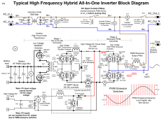
Battery is inherently isolated due to HF step up transformer unless batt- and PV- are tied together internally. High voltage PV input AIO inverters have MPPT out connect direct to HVDC bus feeding non isolated DC-AC converter.Aren’t most solar (outside of microinverter) MPPT / AIO non isolated in 2023?
OK. Non isolated inverter doesn’t bother me that much. Both sides (PV and AC) are at comparable voltages anyway for safety considerations. EG if you have a 350VDC string, does it really matter that it’s not isolated from something that is 350V p-p (sure AC and DC have different human safety properties, as does pulsed DC)Battery is inherently isolated due to HF step up transformer unless batt- and PV- are tied together internally. High voltage PV input AIO inverters have MPPT out connect direct to HVDC bus feeding non isolated DC-AC converter.
This is typical AIO high voltage PV input inverter topology. Solark probably is the same. @Solar Guppy can you confirm?FWIW the blocklevel schematic for SolArk and maybe a few others are floating around the forum.
This would save the batteries if such a fault happens. Do you know if these typical Voltronic AIO's clones like EG4-6500, MPPT6549, etc. have these HF step up transformers included? Maybe the EG4-6500EX is different because it has 2 additional DC-DC converters between SCC output and inverters DC bus to reduce the max. 500VDC to bus voltage.Battery is inherently isolated due to HF step up transformer unless batt- and PV- are tied together internally. High voltage PV input AIO inverters have MPPT out connect direct to HVDC bus feeding non isolated DC-AC converter.
They have to have them otherwise how else can they step up 48V to 200 - 400Vdc for the HVDC bus?Do you know if these typical Voltronic AIO's clones like EG4-6500, MPPT6549, etc. have these HF step up transformers included?
It probably has buck-boost MPPT converters since spec sheet states 90VDC - 450VDC MPPT range. Internal inverter DC bus voltage is likely 200Vdc.Maybe the EG4-6500EX is different because it has 2 additional DC-DC converters between SCC output and inverters DC bus to reduce the max. 500VDC to bus voltage.
Thanks for sharing. This isn't really typical in the sense that it only covers lower voltage PV strings (bottom left needs actively wrong text for 100-500VDC MPPTs removed, and changed to buck/boost), and it's very European. America exists too.This is typical AIO high voltage PV input inverter topology. Solark probably is the same. @Solar Guppy can you confirm?
EG4 MPPT 100-48V does #4 by a thing called a breaker. You know what that is, don't you? It's built right on the side of the unit. Once it trips, SCC will begin to shutdown.That's not the isolation being referred to.
You have to understand the Victron rs450 has isolation features that are different from its 250/150V smart/blue solar sccs.
That referenced thread means nothing.
View attachment 182737View attachment 182738View attachment 182739