Does anyone have a single MPP LV6548 connected to a circuit breaker box for AC output? I have searched and it seems everyone who does this has two units connected. I would greatly appreciate a link or pictures showing me what circuit breaker box to buy and how to supply both legs without burning everything down.


You are using an out of date browser. It may not display this or other websites correctly.
You should upgrade or use an alternative browser.
You should upgrade or use an alternative browser.
LV6548 Single Phase Circuit Breaker Box
- Thread starter Espaul
- Start date
I have a sub panel that has two 60a 2 pole breakers as input feeds. There is a mechanical interlock so that only one can be on at a time. This box has slots for 8 of those thin breakers and can be set up to supply 240v loads, with a double breaker.
When I first set it up, I had one inverter. On the 60a breaker that came from the grid, I connected L1 (line 1) to one side of the breaker and I connected L2 to the other side of the breaker. I didn't have any 240v loads. On the 60a breaker for the inverter input, I connected a wire from one side of the breaker and a wire from the other side of the breaker (both wires) to the black/hot on my inverter. The white/neutral of the inverter is then wired to the neutral bar in the breaker box.
If this is confusing in any way, think of this. If you connect your inverter white/neutral to the box neutral and the inverter black/hot to one of the 240v input legs, then only one side of the panel would be powered, but that side would work. Now if you move the black/hot to the other side of the breaker, to feed the other leg, that side would then work. In both cases the same power source is used, so that power source can supply both sides at the same time. In the event you did have a 250v load, that load would effectively be off, but it would have voltage to ground.....not a problem.
I later got a second inverter and connected it normally, but I did run it for a while with the two lines together on one inverter.
Thank you for replying! My inverter will be supplying all power to the sub panel, and the inverter itself will be connected to a breaker on my main panel to be able to bypass directly through if I don't have enough solar/battery power. So if I understand correctly, putting a double pole breaker (designed for 240v) in the sub panel, it will effectively put 120v on both legs of the sub panel and allow me to use it as normal as long as I don't have any 240v loads?I have a sub panel that has two 60a 2 pole breakers as input feeds. There is a mechanical interlock so that only one can be on at a time. This box has slots for 8 of those thin breakers and can be set up to supply 240v loads, with a double breaker.
When I first set it up, I had one inverter. On the 60a breaker that came from the grid, I connected L1 (line 1) to one side of the breaker and I connected L2 to the other side of the breaker. I didn't have any 240v loads. On the 60a breaker for the inverter input, I connected a wire from one side of the breaker and a wire from the other side of the breaker (both wires) to the black/hot on my inverter. The white/neutral of the inverter is then wired to the neutral bar in the breaker box.
If this is confusing in any way, think of this. If you connect your inverter white/neutral to the box neutral and the inverter black/hot to one of the 240v input legs, then only one side of the panel would be powered, but that side would work. Now if you move the black/hot to the other side of the breaker, to feed the other leg, that side would then work. In both cases the same power source is used, so that power source can supply both sides at the same time. In the event you did have a 250v load, that load would effectively be off, but it would have voltage to ground.....not a problem.
I later got a second inverter and connected it normally, but I did run it for a while with the two lines together on one inverter.
Yes if you connect the inverter output to both sides of the 240v input of the sub panel, it will power both sides of the panel back plane with your inverter output.Thank you for replying! My inverter will be supplying all power to the sub panel, and the inverter itself will be connected to a breaker on my main panel to be able to bypass directly through if I don't have enough solar/battery power. So if I understand correctly, putting a double pole breaker (designed for 240v) in the sub panel, it will effectively put 120v on both legs of the sub panel and allow me to use it as normal as long as I don't have any 240v loads?
Ok, that makes sense. I've jumped into this project head first and now I'm beginning to think I should have looked first.
As for the connecting to both sides, is that accomplished by simply feeding one black wire to a double pole breaker, making it a backfed breaker? Or do I need to somehow wire so that two hot wires are coming from the inverter and going directly to the L1, L2 spaces for what is usually grid supply?
I really appreciate the help, I've spent at least 6 hours in the past two days trying to understand this and ended up more confused than I started.
I would not do anything inside the box that might confuse or create problems at a future date. I would run one hot wire to the box and split it into two wires, which would feed the L1 and L2 input, whether those inputs are terminal screws or an input type feed breaker. (maybe you said the same thing but just confirming by rewriting)Ok, that makes sense. I've jumped into this project head first and now I'm beginning to think I should have looked first.
As for the connecting to both sides, is that accomplished by simply feeding one black wire to a double pole breaker, making it a backfed breaker? Or do I need to somehow wire so that two hot wires are coming from the inverter and going directly to the L1, L2 spaces for what is usually grid supply?
I really appreciate the help, I've spent at least 6 hours in the past two days trying to understand this and ended up more confused than I started.
Nothing really wrong with "Ready, Fire, Aim" unless you are in the wrong end of the gun.
Ah, geez. I get it now. I wasn't understanding the one hot wire becoming two. So basically get some correct rated house wire and split the hot from the inverter to supply both legs. As for the ground coming from the inverter, would I just bond the neutral and ground together?I would not do anything inside the box that might confuse or create problems at a future date. I would run one hot wire to the box and split it into two wires, which would feed the L1 and L2 input, whether those inputs are terminal screws or an input type feed breaker. (maybe you said the same thing but just confirming by rewriting)
Nothing really wrong with "Ready, Fire, Aim" unless you are in the wrong end of the gun.
I understand that it's already grounded from the inverter ac input?
Neutral can be confusing. Don't connect inverter Neutral to ground (in your installation case). That is done in your main panel and done in one place only. I have 2 Growatt units that are much like your inverter. Install instructions say...Neutral from main box goes to inverter and also to subpanel neutral. I add...The chassis of your inverter should be connected to an earth ground wire from your main panel. Your sub panel should also be grounded to your main panel earth ground.Ah, geez. I get it now. I wasn't understanding the one hot wire becoming two. So basically get some correct rated house wire and split the hot from the inverter to supply both legs. As for the ground coming from the inverter, would I just bond the neutral and ground together?
I understand that it's already grounded from the inverter ac input?
You're a lifesaver. Thank you so much. I feel there's only a small chance of burning everything up now!Neutral can be confusing. Don't connect inverter Neutral to ground (in your installation case). That is done in your main panel and done in one place only. I have 2 Growatt units that are much like your inverter. Install instructions say...Neutral from main box goes to inverter and also to subpanel neutral. I add...The chassis of your inverter should be connected to an earth ground wire from your main panel. Your sub panel should also be grounded to your main panel earth ground.
My house breaker box is the standard GE type but all my other breakers are the European DIN rail mount types, like this.
 Available as DC for the panels and AC for the 120 volt output.
2P 63A DC400V MCB Solar Energy Photovoltaic (pv) Solar DC Circuit Breaker H6L9 193571273222 | eBay
Find many great new & used options and get the best deals for 2P 63A DC400V MCB Solar Energy Photovoltaic (pv) Solar DC Circuit Breaker H6L9 at the best online prices at eBay! Free shipping for many products!
www.ebay.com
Sorry to come back with yet another question, but I've hit a snag that I can't seem to wrap my head around. This whole time I've understood that with a single LV6548 the AC input would be 120v. After all, Will simply shows plugging it into a 120 receptacle. I have looked for a 120V circuit breaker to feed from my main panel to the Lv6548, and it seems 30amp is the max commonly found. Your response suggests that you fed 240V into the inverter, but I may have misunderstood? Is that a capability even without a second inverter?I have a sub panel that has two 60a 2 pole breakers as input feeds. There is a mechanical interlock so that only one can be on at a time. This box has slots for 8 of those thin breakers and can be set up to supply 240v loads, with a double breaker.
When I first set it up, I had one inverter. On the 60a breaker that came from the grid, I connected L1 (line 1) to one side of the breaker and I connected L2 to the other side of the breaker. I didn't have any 240v loads. On the 60a breaker for the inverter input, I connected a wire from one side of the breaker and a wire from the other side of the breaker (both wires) to the black/hot on my inverter. The white/neutral of the inverter is then wired to the neutral bar in the breaker box.
If this is confusing in any way, think of this. If you connect your inverter white/neutral to the box neutral and the inverter black/hot to one of the 240v input legs, then only one side of the panel would be powered, but that side would work. Now if you move the black/hot to the other side of the breaker, to feed the other leg, that side would then work. In both cases the same power source is used, so that power source can supply both sides at the same time. In the event you did have a 250v load, that load would effectively be off, but it would have voltage to ground.....not a problem.
I later got a second inverter and connected it normally, but I did run it for a while with the two lines together on one inverter.
I think there are two different topics at play here.Sorry to come back with yet another question, but I've hit a snag that I can't seem to wrap my head around. This whole time I've understood that with a single LV6548 the AC input would be 120v. After all, Will simply shows plugging it into a 120 receptacle. I have looked for a 120V circuit breaker to feed from my main panel to the Lv6548, and it seems 30amp is the max commonly found. Your response suggests that you fed 240V into the inverter, but I may have misunderstood? Is that a capability even without a second inverter?
1. When the grid is down, I want my single 120v output inverter to feed a subpanel that has L1 and L2 inputs.
2. When the grid is up, I want my subpanel's L1 and L2 to be on my main panel's L1 and L2 for reasons to keep my house load better balanced and to make my subpanel easy to connect to my main panel. BUT I also want to have my invert's charger connected to the grid so it can keep my battery topped off.
Are those the two topics that you understand to be goals?
You will have to have some sort of transfer switch or two input subpanel with a lockout toggle between the two inputs. My subpanel has 2, 60a two pole breakers with a mechnical interlock to block the one that is off from turning on.
LV6548 charger spec....."120A Utility Charger (120A at 48V = 5.7kW or 48A at 120V)" Yes you will not normally find a 50amp 120v breaker. Edit....Spoke too soon. They do exist.
Ok, so we have slightly different setups it appears. I want my PV/Batteries to power my sub panel at all times unless the grid is needed. So I plan to wire from a breaker in my main panel to my inverter, then from the inverter directly to the sub panel. The LV6548 shows an AC input range of 90-280V AC input. I imagine it would be easier to wire the inverter to a 240VAC breaker if it can accept it, just want to be absolutely sure that it can and that it can reduce that to 120vac output.I think there are two different topics at play here.
1. When the grid is down, I want my single 120v output inverter to feed a subpanel that has L1 and L2 inputs.
2. When the grid is up, I want my subpanel's L1 and L2 to be on my main panel's L1 and L2 for reasons to keep my house load better balanced and to make my subpanel easy to connect to my main panel. BUT I also want to have my invert's charger connected to the grid so it can keep my battery topped off.
Are those the two topics that you understand to be goals?
You will have to have some sort of transfer switch or two input subpanel with a lockout toggle between the two inputs. My subpanel has 2, 60a two pole breakers with a mechnical interlock to block the one that is off from turning on.
LV6548 charger spec....."120A Utility Charger (120A at 48V = 5.7kW or 48A at 120V)" Yes you will not normally find a 50amp 120v breaker. Edit....Spoke too soon. They do exist.
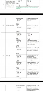
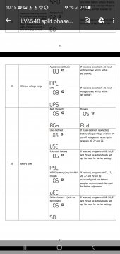
You need to research that in detail to be sure. The 90-280v in would likely be to power the battery charger. My "all in one" has a UPS mode where it passes the grid through to the load and can switch to inverter output when the grid goes down. I think if your's is similar, no it would not "reduce to 120v". HOWEVER, I guess it is possible that the inverter is the output all of the time (running from the battery) and the battery is charging all of the time, powered by the 90-280v......if that were the case then it could have 240v in and 120v out, the output always being the inverter. It should be in the manual.Ok, so we have slightly different setups it appears. I want my PV/Batteries to power my sub panel at all times unless the grid is needed. So I plan to wire from a breaker in my main panel to my inverter, then from the inverter directly to the sub panel. The LV6548 shows an AC input range of 90-280V AC input. I imagine it would be easier to wire the inverter to a 240VAC breaker if it can accept it, just want to be absolutely sure that it can and that it can reduce that to 120vac output.
On mine, I have a meter on the output. When I am on the grid in UPS mode, my output is 124v (my grid voltage). When on the inverter, my output is 120v. So it is pretty clear the inverter is just passing the grid to the output (not adjusting voltage).
That's what I am a little confused about. I assume it's only 120 in/ 120 out, but the "Wide AC input range" makes me wonder. I have looked everywhere and the manual/website say nothing more, but I reached out to MPP for clarification. I'll post the answer if I get one back!You need to research that in detail to be sure. The 90-280v in would likely be to power the battery charger. My "all in one" has a UPS mode where it passes the grid through to the load and can switch to inverter output when the grid goes down. I think if your's is similar, no it would not "reduce to 120v". HOWEVER, I guess it is possible that the inverter is the output all of the time (running from the battery) and the battery is charging all of the time, powered by the 90-280v......if that were the case then it could have 240v in and 120v out, the output always being the inverter. It should be in the manual.
On mine, I have a meter on the output. When I am on the grid in UPS mode, my output is 124v (my grid voltage). When on the inverter, my output is 120v. So it is pretty clear the inverter is just passing the grid to the output (not adjusting voltage).
I looked at the manual. The wording and the settings tables/charts are almost exactly what my Growatt manual says.That's what I am a little confused about. I assume it's only 120 in/ 120 out, but the "Wide AC input range" makes me wonder. I have looked everywhere and the manual/website say nothing more, but I reached out to MPP for clarification. I'll post the answer if I get one back!
In the manual I see 90-140v. I don't see 90-280v for the AC input.
Apparently the manual versions are different. I was accidentally looking at 1.0, while version 1.2 is corrected.I looked at the manual. The wording and the settings tables/charts are almost exactly what my Growatt manual says.
In the manual I see 90-140v. I don't see 90-280v for the AC input.
Attachments
So I think you are back to the question, Do you want to use the inverter in UPS mode where it can pass the grid to your sub panel? Or is it okay that you have to flip a transfer switch to move your subpanel from Grid to Inverter?Apparently the manual versions are different. I was accidentally looking at 1.0, while version 1.2 is corrected.
Yes to the 1st question means you need to seek out that 50A 120v breaker and feed the subpanel with one leg of your main power
Yest to the 2nd question means you could feed the subpanel with 2 legs and then when you switch to inverter, let the inverter feed both sides with one leg. In this mode the breaker to the inverter would be just for charging power and not for feed through.
I bought a 50 amp breaker and wired into one leg of the panel to use as my "main". I have yet to connect the other leg because I don't have enough solar to justify moving over other breakers.@Espaul how did you ever make out with this? I am trying to figure out how to get my LV6548 to a breaker box for the AC out and then feed the breaker box to a sub panel in my cabin. No grid tie.
In my situation I did not bond the neutral/ground, as it's already bonded in the main panel that is connected to the grid. In your situation without grid power, I'm honestly not sure if you would need to bond them or not.
If you would like, I'd be more than happy to take a few pictures of my setup in a few days. It isn't "pretty" right now but I've been running it for several months now and not had any issues. Just need to re-route some wires for cosmetic purposes.
Similar threads
- Replies
- 15
- Views
- 463