Sverige
A Brit in Sweden
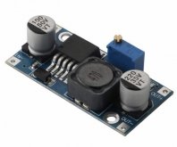
I’m planning on using generic, cheap LM2596 DC/DC converters to drop my DC bus voltage from around 14V (4S LiFePO4) to the 12V, 9V and 5V my devices will require. All load devices are very low power, around 3W continuous will be drawn from each of the voltages (5, 9 &12V), so well within the rated 3A output current of this particular device which I’ve ordered:
Hopefully that listing displays in English. It’s German amazon.
So my questions, to those with experience using these devices:
1) I understand the device efficiency is affected primarily by the size of the voltage drop from input to output, so if I need 5, 9 and 12V all in one location, is it better to daisy-chain the converters, so the output of the 12V converter becomes input of the 9V converter, and likewise the 5V converter is connected at the end of the chain? This way the second and third converters are dropping their input voltage less than if all three devices were paralleled up with 14V input. Ok, the current for all load devices then flows via the 12V converter, but total load connected to all three converters is under 10W, so even with some conversion inefficiencies the first converter is only seeing something like 1A total output current. All converters will be physically in the same place, so no cable runs (more than 10cm or so) to think about.
2) Will cumulative ripple become a concern with three devices all in a chain?
3) Does anyone know if it’s beneficial, or necessary to solder a big electrolytic capacitor across the output side of these converters, or do they have enough smoothing?
4) Has anyone tested the efficiency of these devices to see if they live up to the claimed “up to 92%”? Of course “up to” is fairly meaningless as a spec!
5) Does anyone know if these things have a habit of drifting from their set point output voltage over time? Do I need to keep checking to make sure my 5V DC isn’t creeping upwards at all?
Thanks all.
RUNCCI-YUN 8Pcs LM2596S DC-DC Buck Converter Set, 3.2-46V bis 1.25-35V Step-Down Spannungsregler Abwärtswandler, Stromversorgung Step Down Modul, für Arduino: Amazon.de: Gewerbe, Industrie & Wissenschaft
RUNCCI-YUN 8Pcs LM2596S DC-DC Buck Converter Set, 3.2-46V bis 1.25-35V Step-Down Spannungsregler Abwärtswandler, Stromversorgung Step Down Modul, für Arduino: Amazon.de: Gewerbe, Industrie & Wissenschaft
www.amazon.de
Hopefully that listing displays in English. It’s German amazon.
So my questions, to those with experience using these devices:
1) I understand the device efficiency is affected primarily by the size of the voltage drop from input to output, so if I need 5, 9 and 12V all in one location, is it better to daisy-chain the converters, so the output of the 12V converter becomes input of the 9V converter, and likewise the 5V converter is connected at the end of the chain? This way the second and third converters are dropping their input voltage less than if all three devices were paralleled up with 14V input. Ok, the current for all load devices then flows via the 12V converter, but total load connected to all three converters is under 10W, so even with some conversion inefficiencies the first converter is only seeing something like 1A total output current. All converters will be physically in the same place, so no cable runs (more than 10cm or so) to think about.
2) Will cumulative ripple become a concern with three devices all in a chain?
3) Does anyone know if it’s beneficial, or necessary to solder a big electrolytic capacitor across the output side of these converters, or do they have enough smoothing?
4) Has anyone tested the efficiency of these devices to see if they live up to the claimed “up to 92%”? Of course “up to” is fairly meaningless as a spec!
5) Does anyone know if these things have a habit of drifting from their set point output voltage over time? Do I need to keep checking to make sure my 5V DC isn’t creeping upwards at all?
Thanks all.