The pdf I'm looking at is in English.
Which model? SGI 9K, SGI 10K or SGI
SGI 9K
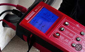
I assume you were using the tests on page 22 of the pdf to look for a PV earth fault. Like I said, it might be easier/pinpoint a problem to measure VMP under load to see if there is a fault in the wiring/high resistance. Open circuit tests only measure voltage potential, when under load is when high resistance will appear. I think your problem is possibly PV string voltage dropping below the MPPT operating range or resistance in the positive of negative PV wires.
And what’s the MPPT operating range ?
As i previously said the inverter works fine even if one string has a VMP < 300 volt.
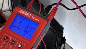
The Panel‘s rated voltage ( U mppt ) = 27.2 volt
You are seeing FS 19 for the fault?
Yes error 19 ( isolation fault ) pops up
From what I can see, the inverter is measuring the voltage of PV + to earth and PV - to earth. There is a ratio it is looking for. However, high resistance on either +/- can affect that ratio and the inverter faults as it is only programmed to set a fault code for PV insulation.
Yes that’s exactly what I tried to measure, however I measured in the night, so far didn’t measure voltage to earth in the day !
. In the case of high resistance in a circuit however, you should be able to find it using voltage and voltage drop tests.
How ?
Here are the specs of the panels :
Rated power 220
Rated voltage ( U mpp ) 27.2
Rated current ( I mpp) 8.07
Open circuit voltage ( U oc) 33.1
Short circuit current ( I sc) 8.80
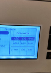
Output on a relative cold day ( error occurring : inverter showing an error ) :
Voltage. Current. Power
#1String 621,9 0,00 0,00
#2String 314,2 0,00 0,00
Output on another day ( no error : inverter working fine ) :
Voltage. Current. Power
#1String 433,9. 0,25 0,11
#2String 215,4. 0,25 0,05
Output on another cold day ( error occurring: inverter showing an error ) :
Voltage. Current. Power
#1String 559,2. 0,00. 0,00
#2String 284,1. 0,01. 0,00
Output today - sunny day ( no error : inverter working fine ) :
Voltage. Current. Power
String 1. 584,9. 5,17. 2,84
String 2 269,1. 5,62. 1,51
All these data were shown on the display of the inverter