


sunshinestatestreaming
New Member
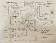
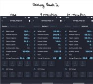
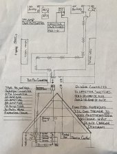
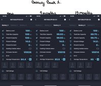
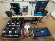
Going all out with a Renogy install using 6x100 Ah Smart lithium that renogy said wouldn’t work as it may cause balancing issues, however I am not seeing it yet. Has anyone else tried this and if so how did it work?
Attachments
-
 39A03F8D-5B13-474D-A378-92BA7A95FC12.jpeg329.7 KB · Views: 54
 -
 8D1788B5-E06E-45A0-AB6D-D63E4544D378.jpeg488.4 KB · Views: 39
 -
 A2167538-DB67-475E-AA40-D291C0ED52E8.jpeg191.2 KB · Views: 36
 -
 55EB8A89-C5D5-43C0-B060-F17C45002891.jpeg498.9 KB · Views: 52
 -
 70603BB1-8A88-4390-9996-8E44AB403573.jpeg241.7 KB · Views: 61


 I’ll be happy to add something to the end of it to upset them all, but it will have to await me having more time to write.