SunCatcher
New Member
- Joined
- Dec 24, 2021
- Messages
- 62
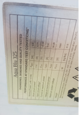
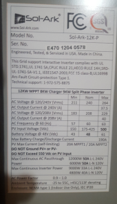
After much soul searching and pulling out of hair  things are slowly coming together. I had no idea just what I signed up for. Because of the internet and places like this I have most of the answers I needed to pull this off. So there are just a few questions left. The system uses the Solark 12K inverter and 28 330 watt panels (I think 37 volt?) I am in oregon if that is relevant.
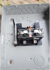
#1 My array is 350 feet from the house and the D.C. has three strings at about 370, 340 and 340 Volts each. Solark does not show a DC shutoff going into the house. I could be wrong but I think it is because most systems are roof mount and very few are 350 feet away from the house. Thus I have to run my array at high voltage to keep the wiring size down. Solark does show the knife edge going from the inverter to meter (AC) that prevents Inverter from backfeeding into the grid during an emergency. I also shows the emergency shutdown. There is no mention anywhere with Solark showing a DC knife edge shutoff.
My concern is that during an emergency the fire fighting crew will think that they have shut off the electricity in the house and yet there are three DC circuits running dangerous high voltage into the house to the Inverter. So does anyone have information on this. The county here is low staffed due to covrid and will be reopening soon but I am trying to move forward if at all possible. Any information on this would be very much appreciated.
Les
things are slowly coming together. I had no idea just what I signed up for. Because of the internet and places like this I have most of the answers I needed to pull this off. So there are just a few questions left. The system uses the Solark 12K inverter and 28 330 watt panels (I think 37 volt?) I am in oregon if that is relevant.#1 My array is 350 feet from the house and the D.C. has three strings at about 370, 340 and 340 Volts each. Solark does not show a DC shutoff going into the house. I could be wrong but I think it is because most systems are roof mount and very few are 350 feet away from the house. Thus I have to run my array at high voltage to keep the wiring size down. Solark does show the knife edge going from the inverter to meter (AC) that prevents Inverter from backfeeding into the grid during an emergency. I also shows the emergency shutdown. There is no mention anywhere with Solark showing a DC knife edge shutoff.
My concern is that during an emergency the fire fighting crew will think that they have shut off the electricity in the house and yet there are three DC circuits running dangerous high voltage into the house to the Inverter. So does anyone have information on this. The county here is low staffed due to covrid and will be reopening soon but I am trying to move forward if at all possible. Any information on this would be very much appreciated.
Les